Steel grid plate composite blade shearing machine

A steel grating and blade technology, which is applied in the direction of shearing machine equipment, shearing machine accessories, shearing devices, etc., can solve the problems of large noise and pollution, material loss, and slow speed, and achieve fast cutting and cutting , Create an effect that is easy to use

Inactive Publication Date: 2008-03-19
JIANGSU POLYTECHNIC UNIVERSITY
View PDF0 Cites 9 Cited by
  • Summary
  • Abstract
  • Description
  • Claims
  • Application Information

AI Technical Summary

Problems solved by technology

The steel grating is welded by the above-mentioned multi-row vertical steel plate bearing the main load and the multi-row horizontal twisted steel perpendicular to it by automatic pressure welding machine, and then according to the actual situation of the place of use, the steel grating The b

Method used


Image

  • Steel grid plate composite blade shearing machine
  • Steel grid plate composite blade shearing machine

Examples


Embodiment Construction

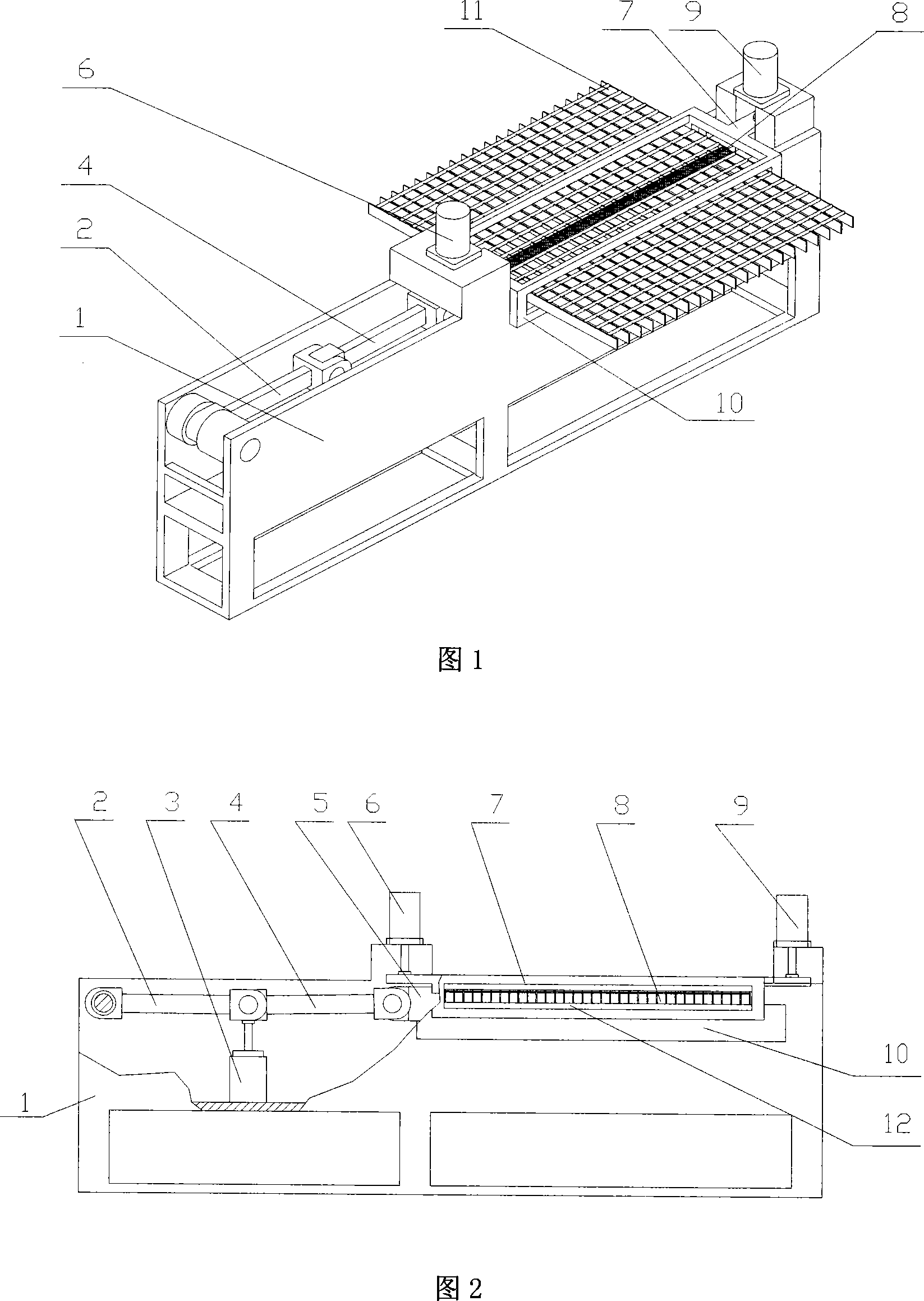
[0012] As shown in Fig. 1, Fig. 2 and Fig. 4, a bed table 12 is arranged inside the machine body 1 of the shearing machine. The bed table 12 is fixed on the bed base 10. The bed table 12 is in the shape of a horizontal platform with a wide opening. Upper narrow trapezoidal groove. An oil cylinder 3 is provided in the inner cavity on the left side of the fuselage 1, and the movable push rod of the upper end of the oil cylinder 3 can move up and down. At the upper end of the movable push rod, the left end of the connecting rod 2 is fixed at the upper left of the fuselage 1, and the connecting rod 2 The right end and the left end of the connecting rod 4 are connected to form a common end, and the common end is connected to the movable push rod of the oil cylinder 3. A guide block 5 is arranged in the middle of the fuselage 1, and its left side is in tight contact with the right end of the connecting rod 4.

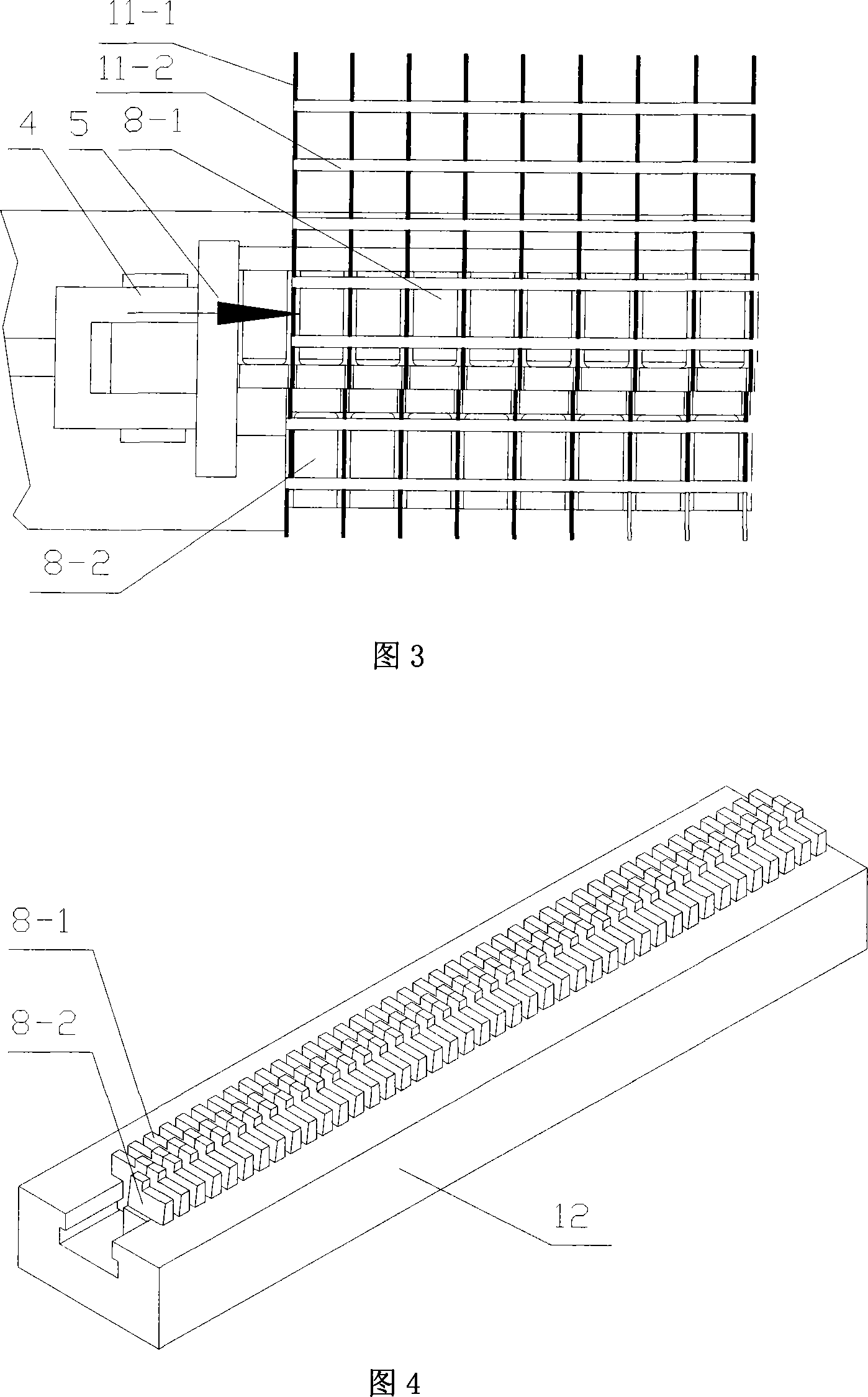
[0013] Two rows of combined blades 8 are arranged in the bed 12, which are m...


PUM


Abstract

The invention discloses a combined blade shearing machine of the steel grid plate, comprising a main body and a plate arranged inside the main body. The invention is characterized in that a hydrocylinder is arranged inside the main body; a push rod of the hydrocylinder and a connecting bar are connected with a common end of the connecting bar; one end of the guide block closely touches one side of the connecting bar; two rows of the combined blades are arranged in a dovetail groove along the plate, wherein one row of the combined blades are dead blades and the other row of the combined blades are moveable blades. The moveable blades corresponding to the connecting bar closely touches the other side of the guide block and are pushed by the connecting bar to laterally move. The invention has two rows of the combined blades, one row of which are relatively fixed and the other row of which have lateral shearing motion caused by the connecting bar which is pushed by the hydrocylinder. Meanwhile, the ascending motion and the descending motion of two elevator hydrocylinders make the sheared steel grid plate compressed and pushed out. The invention has simple structure and is easy to be manufactured and used. Therefore, the invention can shear the steel grid plate well and fast.

Description

Technical field [0001] The invention relates to a shearing machine, in particular to a shearing machine for cutting steel gratings. Background technique [0002] Steel gratings are widely used in work platforms, treads, planks, protective fences, etc. in many industries. The steel grating consists of multiple rows of loaded flat steels and multiple rows of horizontal bars arranged at a certain distance between warp and weft to form a grid. The radial direction is the loaded flat steel. Generally, vertical steel plates are used, that is, the length of the steel grating; the latitude is horizontal The rod generally uses horizontal twisted steel, that is, the width direction of the steel grating. The steel grating is welded by the above-mentioned multi-row vertical steel plates that bear the main load and the multi-row horizontal twist steel orthogonal to it by an automatic pressure welding machine, and then according to the actual situation of the use place, the steel grating The b...

Claims


Application Information

Patent Timeline
IPC IPC(8): B23D15/14B23D33/02B23D15/04
Inventor 葛乐通施昱
Owner JIANGSU POLYTECHNIC UNIVERSITY
Why Eureka
Try Eureka