Display panel thin grinder

A display panel and grinding machine technology, applied in the direction of optical surface grinders, grinding machines, grinding/polishing equipment, etc., can solve the problems of shortening the life of polishing pads, agglomeration, and not easy to find, so as to save maintenance time and flow distribution Uniformity, the effect of reducing production costs

Inactive Publication Date: 2008-03-19
AU OPTRONICS (SUZHOU) CORP LTD
View PDF0 Cites 5 Cited by
  • Summary
  • Abstract
  • Description
  • Claims
  • Application Information

AI Technical Summary

Problems solved by technology

[0004] The disadvantage of this structure of grinding equipment is that the flow distribution of the grinding liquid supply is not uniform, resulting in inconsistent polishing rates in different areas of the glass substrate, increasing the working time (tack time) and increasing manufacturing costs.
[0006] However, there are still some disadvantages in the structure of this water pipe access at present: (1) after the solenoid valve stops water supply, a section of water will remain in the water pipe between the solenoid valve and the overhead supply tank (head tank), and the water pipe in the water pipe The water will flow out uncontrollably. When the polishing pad is pressed, the water may cause the polishing pad to be not firmly attached, shorten the life of the polishing pad, and increase the cost
); (2) When cleaning the machine, the grinding fluid remaining in the grinding fluid pipeline cannot be cleaned with water. If the machine is shut down for a long time, the grinding fluid will agglomerate in the pipeline and it is not easy to find and clean; agglomeration, Foreign matter that cannot be cleaned can cause blockages in the pipeline and, if hard particles flow into the grinding system, cause fragments

Method used


Image

  • Display panel thin grinder

Examples


Embodiment

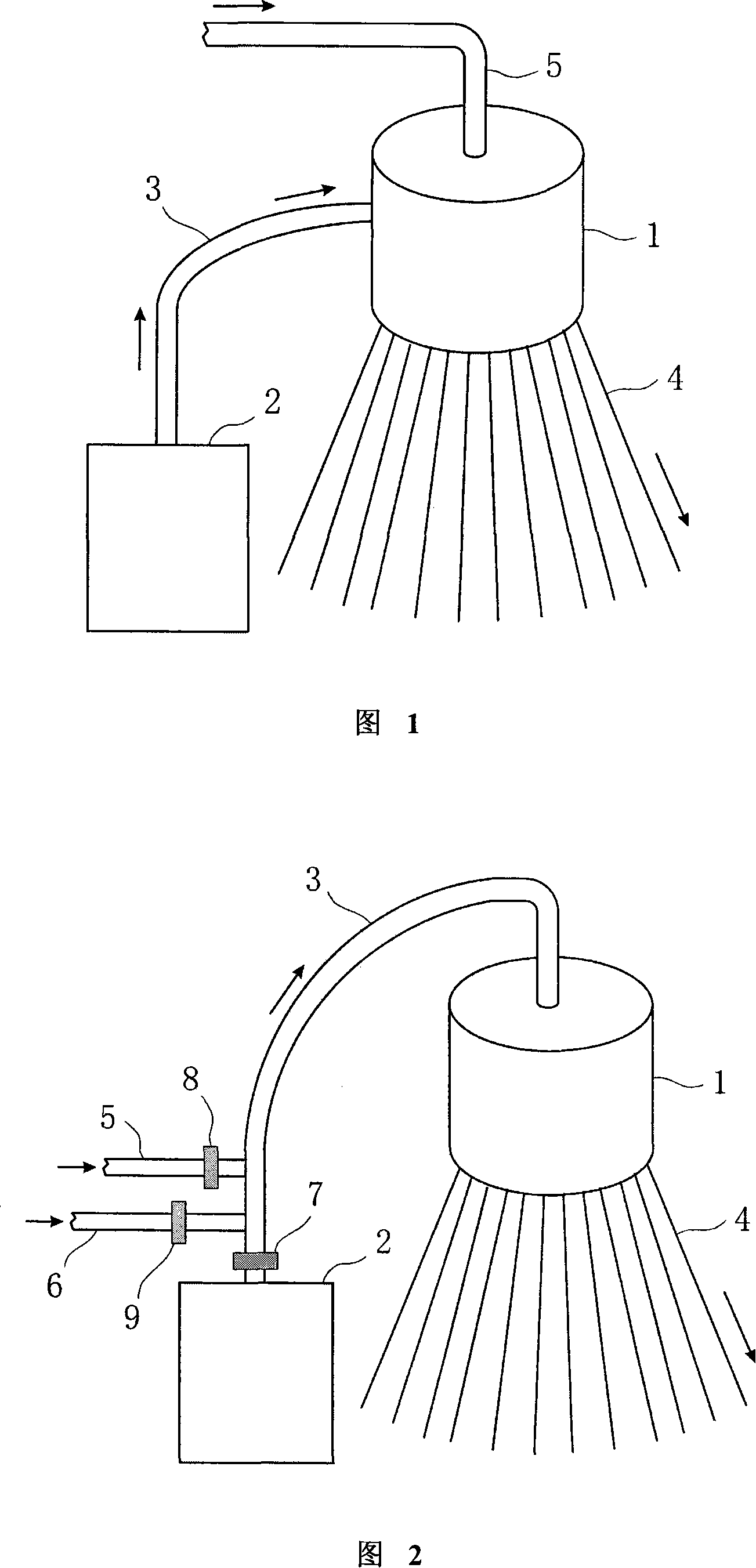
[0026] Embodiment: as shown in Fig. 2, a kind of display panel thinning grinder, it comprises overhead feeding tank 1, grinding fluid storage tank 2, grinding platform, connection grinding fluid storage tank 2 and overhead feeding tank 1 The grinding liquid pipeline 3 and 60 conduits 4 connecting the overhead feed tank and the grinding platform, the connection ports between the conduits 4 and the overhead feed tank 1 are distributed at the bottom of the overhead feed tank 1 .

[0027] The grinding liquid pipeline 3 is connected to the top center of the overhead feed tank 1 . At the same time, the water pipe 5 and the compressed air pipe 6 for conveying compressed air are respectively connected to the grinding liquid pipeline 3 .

[0028] The access position where the water pipe 5 and the compressed air pipe 6 are connected to the grinding liquid pipeline 3 is as close as possible to the grinding liquid pipe control valve 7 . Because the access position of the water pipe 5 is ...


PUM


Abstract

The invention discloses a display-panel thinning grinding machine, consisting of an overhead supply tank (1), a storage tank for grinding fluid (2), a grinding platform, a grinding fluid pipe (3) connecting with the storage tank for grinding fluid (2) and the overhead supply tank (1) and a plurality of catheters (4) connecting with the overhead supply tank (1) and the grinding platform, wherein the connecting ports between the catheters (4) and the overhead supply tank (1) are located at the bottom of the overhead supply tank (1), and the grinding fluid pipe (3) is connected from the top central location of the overhead supply tank (1). Besides, a water pipe (5) and a compressed air pipe (6) are respectively connected to the grinding fluid pipe (3). The invention enables the flow of grinding fluid provided to a system is uniform and the grinding efficiency of different regions of a glass substrate keeps the same; at the same time, the invention can clean the grinding fluid left in the pipe in a better way, thereby avoiding the impact of grinding fluid on a attached polishing pad, lowering cost, facilitating cleaning, saving maintenance time and improving yields.

Description

technical field [0001] The invention belongs to a display panel manufacturing equipment, in particular to a display panel thinning grinder. Background technique [0002] Display panels such as liquid crystal display screens have been more and more applied to portable electronic devices (such as notebook computers, PDAs, etc.), and weight is one of the focuses of portable products. Every gram of weight reduction is valuable. of. Making the glass of the liquid crystal display as thin as possible is one of the ways to reduce the weight. Today, the glass thickness of some finished LCD screens has been reduced from the usual 0.9 mm to 0.2 mm. To achieve such a glass thickness, it needs to be achieved through a grinding process. [0003] At present, the commonly used grinding equipment for display panel thinning can be referred to as shown in Figure 1, which includes an overhead feed tank, a grinding liquid storage tank, a grinding platform, connecting the grinding liquid stora...

Claims


Application Information

Patent Timeline
Patent Type & Authority Applications(China)
IPC IPC(8): B24B13/015B24B57/02
Inventor 夏家涛李尚
Owner AU OPTRONICS (SUZHOU) CORP LTD
Why Eureka
Try Eureka