Eureka AIR delivers breakthrough ideas for toughest innovation challenges, trusted by R&D personnel around the world.

Rotating type diffused fluorescent chromatographic imaging system

A fluorescence tomography and imaging system technology, applied in the field of biofluorescence tomography, can solve the problems of limited imaging quality and limited data volume, and achieve the effect of stable and effective data collection

Inactive Publication Date: 2008-03-26
HUAZHONG UNIV OF SCI & TECH
View PDF1 Cites 20 Cited by
  • Summary
  • Abstract
  • Description
  • Claims
  • Application Information

AI Technical Summary

Problems solved by technology

Continuous light source irradiation and camera data collection are also used, but since the light source and camera are fixed, the amount of collected data is limited, and the imaging quality is limited by the amount of collected data

Method used


Image

  • Rotating type diffused fluorescent chromatographic imaging system
  • Rotating type diffused fluorescent chromatographic imaging system
  • Rotating type diffused fluorescent chromatographic imaging system

Examples


example 1

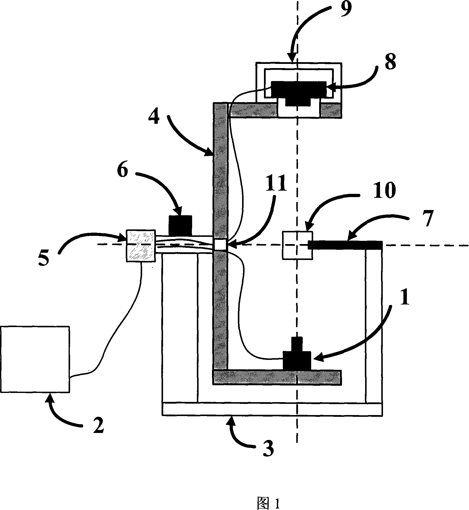
[0039] The parameters of semiconductor laser 1 are: 652nm / 50mW, spot diameter 0.38mm, 180° up and down offset 0.355mm. The imaging sample 10 is a cylindrical glass tube with an outer diameter of 25.4 mm and a wall thickness of 1 mm. The glass tube is filled with 1% Intrilipid aqueous solution and two small transparent plastic tubes. Both plastic tubes were filled with 2.0% Intrilipid aqueous solution, and two drops of ink were added in one plastic tube 17 (diameter 4 mm), and one drop of ink was added in the other plastic tube 18 (diameter 3.6 mm). Two plastic pipes 17, 18 are parallel, and the central axes of the two pipes are 8.6mm apart. The structural schematic diagram of the imaging sample 10 is shown in FIG. 5 a , a three-dimensional schematic diagram of a glass tube imaging sample, and FIG. 5 b , a schematic cross-sectional diagram of a glass tube imaging sample. The system of the present invention is used to collect data, and the absorption coefficient curve of the im...


PUM


Abstract

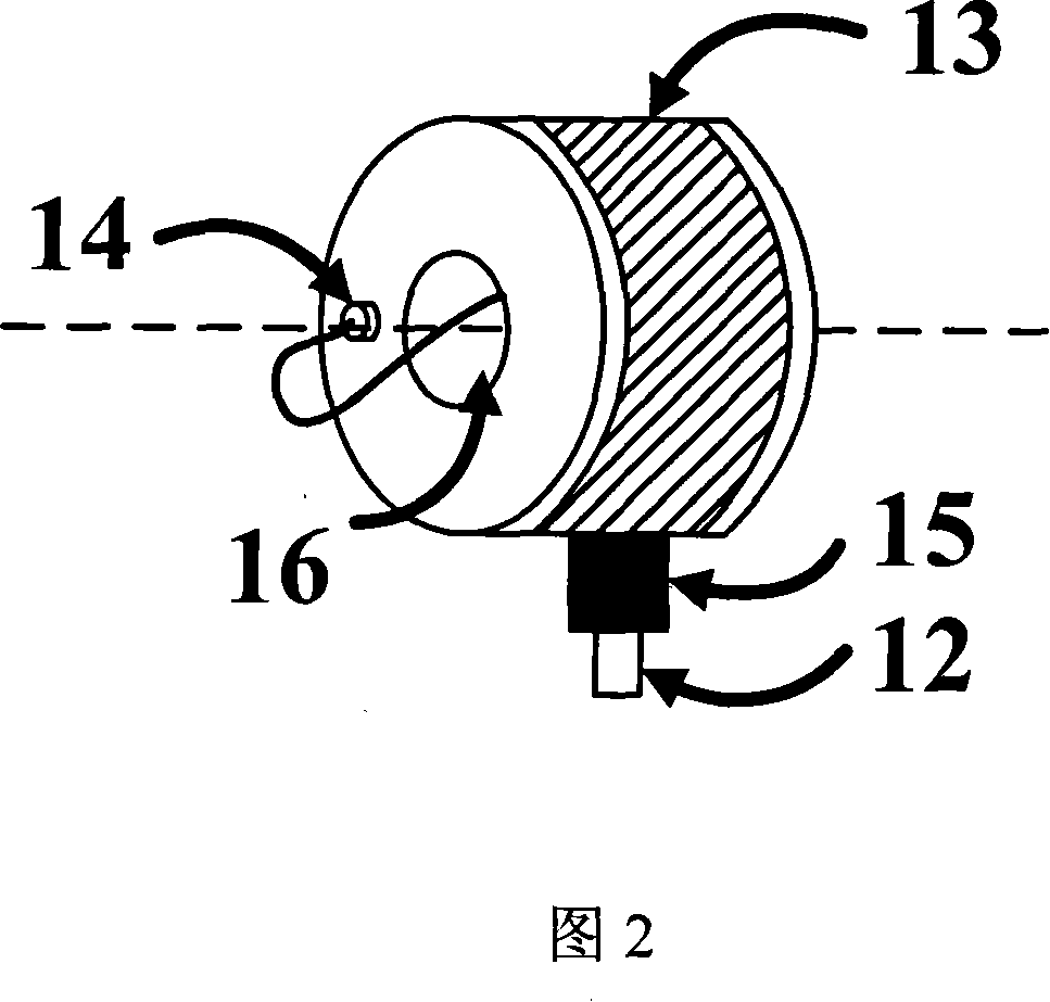
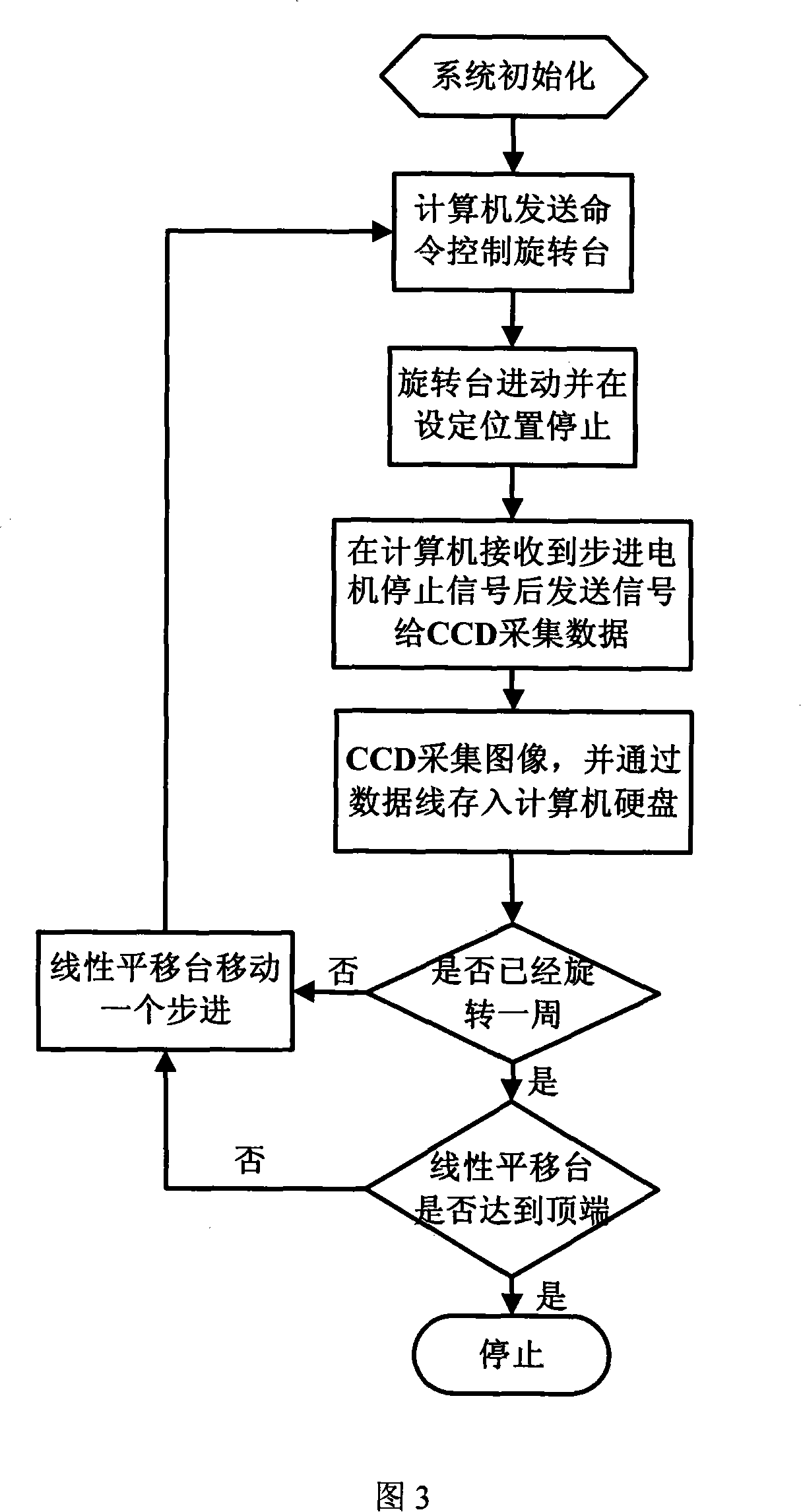
The present invention relates to a rotary type diffusion fluorescence tomography system. Said system includes the following several portions: semiconductor laser, computer, rotary working table, stepping motor and CCD camera. Said invention also provides its working principle and concrete operation method.

Description

technical field [0001] The invention belongs to biological fluorescence tomography technology, and relates to a rotary fluorescence tomography technology (fluorescence diffuse optical tomography, FDOT) based on near-infrared light diffusion properties, specifically a rotary diffusion fluorescence tomography system, which is suitable for In vivo non-invasive detection of carcinogenesis in small animals. technical background [0002] Using the diffusion properties of near-infrared light, the in vivo non-invasive detection technology of small animals is a promising optical imaging technology. Compared with microscopic imaging and optical weak coherence tomography technology, it has the highest imaging depth The deepest optical imaging method. There is a US Patent No. 7.107.116 applied for abroad. The technical means used in this invention is to squeeze the small animals into a flat shape, and use the diffusion equation in the semi-infinite medium to derive the optical paramete...

Claims


Application Information

Patent Timeline
Patent Type & Authority Applications(China)
IPC IPC(8): A61B5/00A61B10/00G06F17/11
Inventor 骆清铭曾绍群毕昆全国涛
Owner HUAZHONG UNIV OF SCI & TECH
Why Eureka
Eureka Blog
Learn More