Flood discharging method and flood discharging tunnel employing rotational flow and strong moisture mixing energy dissipation

A technology of flood discharge tunnel and water gas, which is applied in water conservancy projects, sea area engineering, coastline protection, etc. It can solve problems such as difficulty in ensuring project safety, high flow velocity at the outlet of flood discharge tunnel, damage, etc., and achieve the effect of preventing cavitation and saving engineering costs

Inactive Publication Date: 2008-03-26
CHINA INST OF WATER RESOURCES & HYDROPOWER RES
View PDF0 Cites 28 Cited by
  • Summary
  • Abstract
  • Description
  • Claims
  • Application Information

AI Technical Summary

Problems solved by technology

The destruction of many spillway tunnels all over the world is caused by cavitation (the steel bars on the bottom plate are broken, washed into huge deep pits, and the concrete bottom plate more than 100 meters long is lifted), such as Hoover in the United States, Huangwei Dam, China's Liujiaxia and Ertan Hydropower Station and other flood discharge tunnels have all suffered serious damage accidents, direct...

Method used


Image

  • Flood discharging method and flood discharging tunnel employing rotational flow and strong moisture mixing energy dissipation
  • Flood discharging method and flood discharging tunnel employing rotational flow and strong moisture mixing energy dissipation
  • Flood discharging method and flood discharging tunnel employing rotational flow and strong moisture mixing energy dissipation

Examples


Embodiment 1

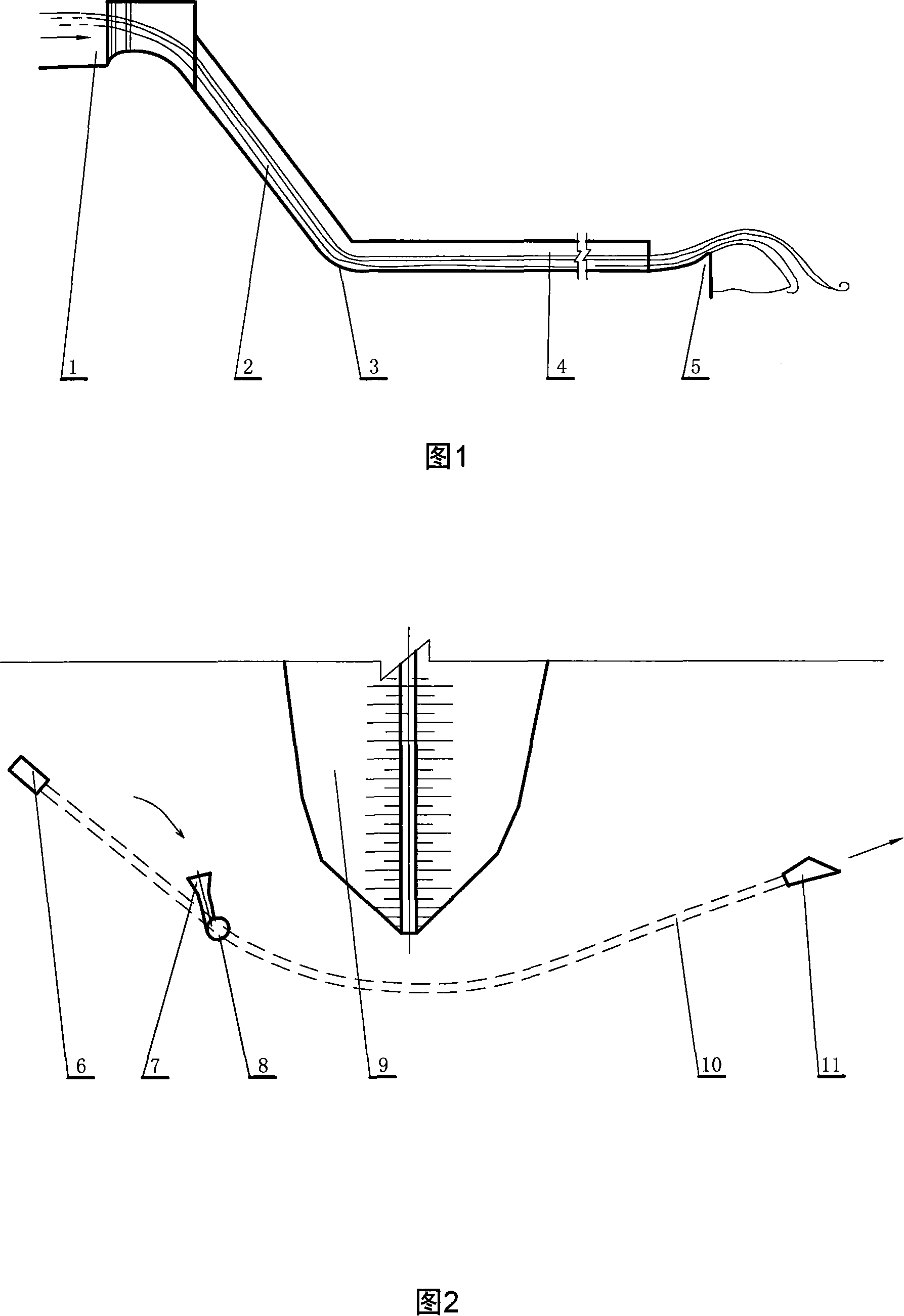
[0021] As shown in Figure 1, a traditional flood discharge tunnel consists of a water inlet 1, an inclined shaft 2, an anti-arc section 3, an open flow outlet tunnel (diversion tunnel utilization section) 4, and an outlet deflector (or stilling pool) 5. The flood discharge process of the traditional flood discharge tunnel can be simply described as: when the flood from the upstream reservoir enters the flood discharge tunnel through the water inlet, since there is no energy dissipation facility, the kinetic energy converted from the potential energy of the high water level difference is concentrated at the exit of the anti-arc section at the bottom of the tunnel. The pressure is low, the flow rate is the highest, and the cavitation number of the leakage flow is the smallest. It is a cavitation sensitive area and is prone to cavitation damage. Although ventilation slots can be set up from the upstream of the anti-arc section to add air to the anti-arc section to reduce cavitatio...

Embodiment 2

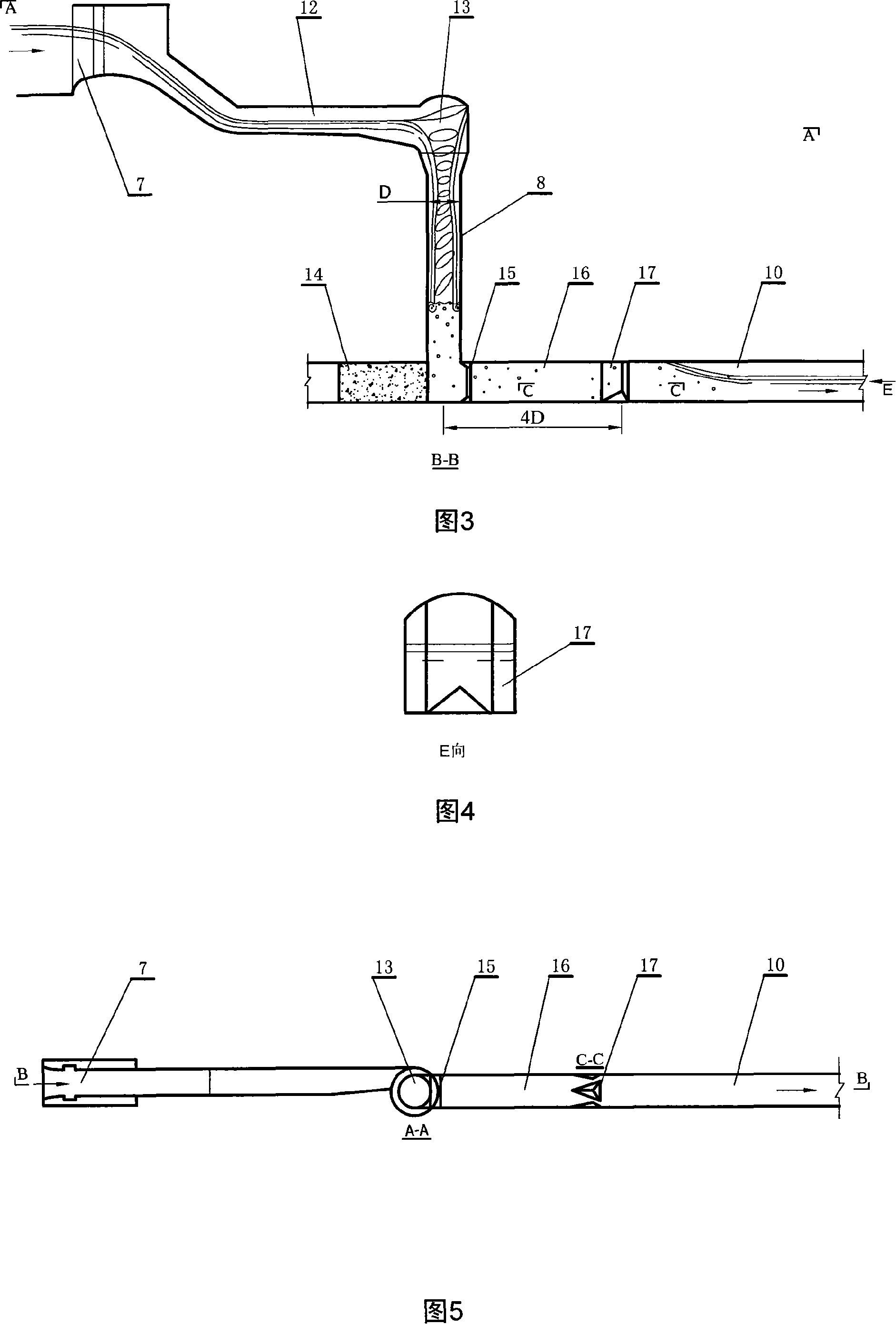
[0029] This embodiment proposes a swirl shaft (water flow rotates around the axis of the shaft) combined with a pad pond for energy dissipation and flood discharge, which is an improvement of the first embodiment.

[0030] As for the vortex chamber structure of the swirl shaft, it was used in small urban drainage projects in Italy as early as the 1960s. Due to its complex structure and relatively large size, it has not yet been applied to large and medium-sized hydropower projects. The simple swirling vortex chamber structure designed by the Chinese Academy of Water Sciences in 1995 was first applied to the flood discharge tunnel of the Shapai Hydropower Station in Sichuan, opening the door for hydropower engineering applications. However, the Shapai-type flood discharge tunnel still needs to excavate a stilling well under the tunnel floor, which is difficult to construct. The energy dissipation rate in the tunnel only reaches 70%, which still cannot meet the requirements of hi...

Embodiment 3

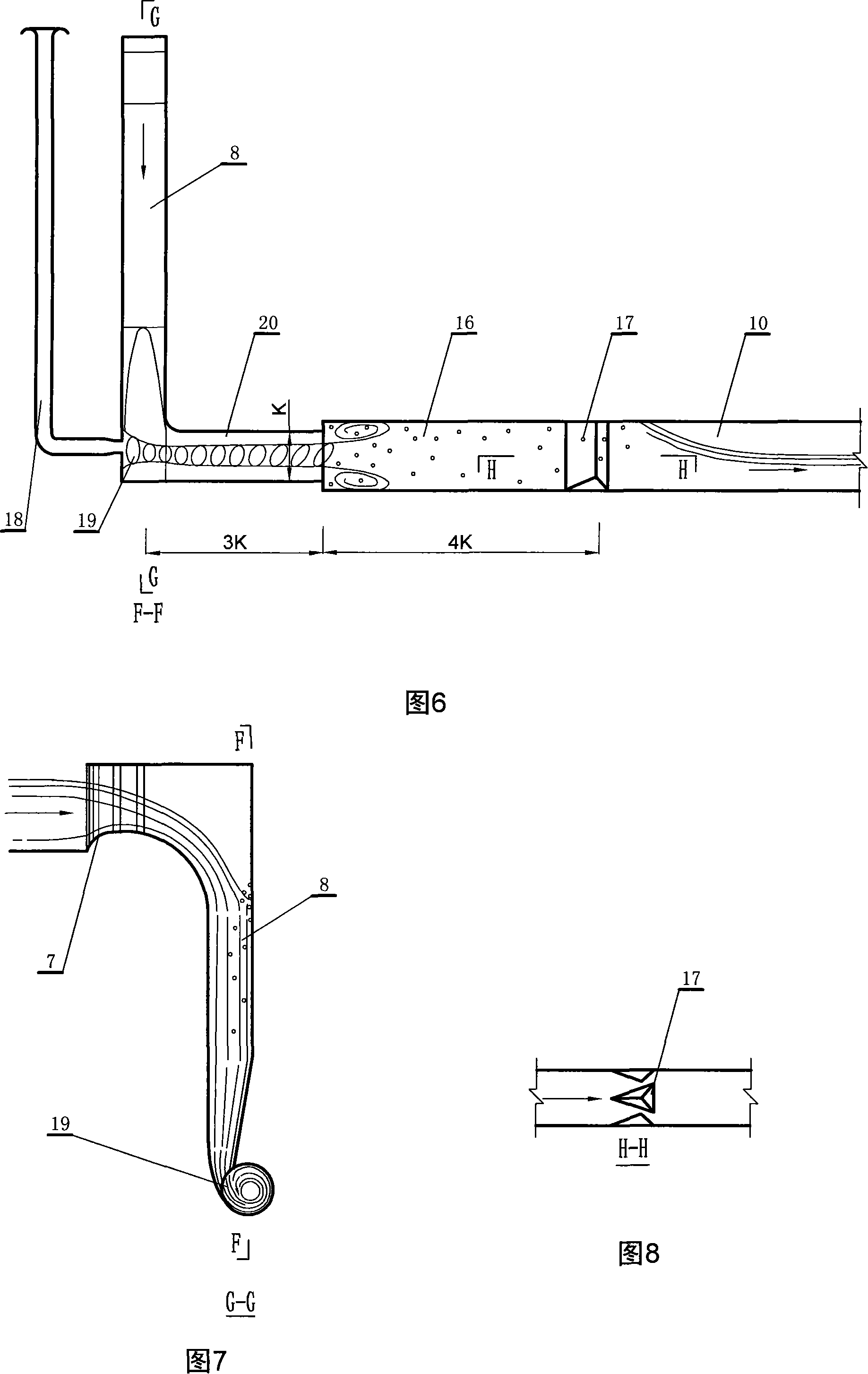
[0040] This embodiment describes a flood discharge method using a section of horizontal swirl tunnel (the water flow rotates around the axis of the flat tunnel) to connect the pad pond for energy dissipation. The facilities used are mainly composed of vertical shaft 8, ventilation shaft 18, swirl chamber 19, swirl hole 20, water cushion pond 16, and water outlet hole 10. Among them, the swirl chamber, swirl tunnel, water cushion pond and flood discharge tunnel are all built in the diversion tunnel. The schematic diagram of its plane layout is still shown in Fig. 2, and the flow process of water is shown in Fig. 6 and Fig. 7 .

[0041] The steps of flood discharge and energy dissipation are: the water flow enters the shaft from the water inlet, rotates in the swirl chamber and the swirl hole to form a spiral flow with a cavity, and makes a three-dimensional rotation and diffusion motion at the inlet of the pad pond to carry out a strong force. The water and air are mixed and s...


PUM


Abstract

The present invention relates to flood discharge method and flood discharge tunnel dissipating energy by means of eddying flow and intense water-air mixing, and is especially one flood discharge tunnel for high water head large hydraulic power project. The flood discharge tunnel includes one water inlet in the upstream of dam, one eddy flow and fall head energy dissipating facility connected to the water inlet and provided with well, one water cushion pond with one waterproofing pier in the exit for further energy dissipating, one water output tunnel connected to the water cushion pond and one water outlet. The flood discharge tunnel has one energy dissipating rate as high as 90 %, and can control the outlet flow rate and prevent cavitation erosion, scouring and atomizing effectively.

Description

technical field [0001] The invention relates to a flood discharge method and a flood discharge tunnel using swirling flow and strong water-air mixing energy dissipation, which is a new type of flood discharge tunnel in which a swirl shaft (or a horizontal swirl tunnel) is combined with a pad pond for energy dissipation. The hole can be mixed with a large amount of air for strong water-air turbulent mixing, which can eliminate 90% of the flood energy released by the high-water level retaining dam, so it can avoid the damage of high-speed water to hydraulic structures and the erosion of downstream river beds and cause Atomization leads to instability of bank slopes, and the invention is applicable to flood discharge tunnels of large-scale hydropower projects with high water heads. Background technique [0002] The disadvantages of traditional flood tunnels are many. First of all, this kind of flood discharge tunnel must be built straight on the plane without turning. However,...

Claims


Application Information

Patent Timeline
IPC IPC(8): E02B8/06
Inventor 董兴林杨开林王涛
Owner CHINA INST OF WATER RESOURCES & HYDROPOWER RES
Why Eureka
Try Eureka