
Light curtain array automatic scoring round target device and method

A light curtain and array technology, applied in the field of automatic target reporting devices for bullet shooting, can solve the problems of complex circuit design, low precision, and high false alarm rate, and achieve the effects of accurate three-dimensional non-contact measurement, overall optimization, and simplified structure

Inactive Publication Date: 2008-03-26
XIAN TECHNOLOGICAL UNIV
View PDF9 Cites 38 Cited by
  • Summary
  • Abstract
  • Description
  • Claims
  • Application Information

AI Technical Summary

Problems solved by technology

Although the acoustic target reporting technology has the advantages of simplicity and convenience, it is susceptible to interference from adjacent targets and has a high false alarm rate. The shooter must shoot vertically to the target surface, otherwise large errors will occur, and when used outdoors, it is vulnerable to The effect of wind speed
With the development of semiconductor optoelectronic technology, target reporting devices based on optoelectronic technology are also emerging, such as Chinese patents CN95206124.4, CN3246740, CN200420007418.7, etc., which use multiple light emitting devices and corresponding receiving devices to form a grid , when the projectile passes through, cover the corresponding light, and detect the output signal of the receiving device at the corresponding position to judge the target position of the projectile. This method of reporting the target has low accuracy and requires multiple photoelectric receivers with excellent performance. Devices and light sources with high parallelism must continuously detect the status of multiple receiving devices during the test process, and the design of the circuit part is relatively complicated
In addition, there is a target reporting method using graphic acquisition technology, which requires an expensive CCD camera and image processing software, and it cannot distinguish between heavy holes and automatic target reporting for burst shooting
[0003] The project team of this invention has searched domestic and foreign patent documents and published journal papers, and has not found any reports or documents closely related to the present invention.

Method used


Image

  • Light curtain array automatic scoring round target device and method
  • Light curtain array automatic scoring round target device and method
  • Light curtain array automatic scoring round target device and method

Examples


Embodiment 1

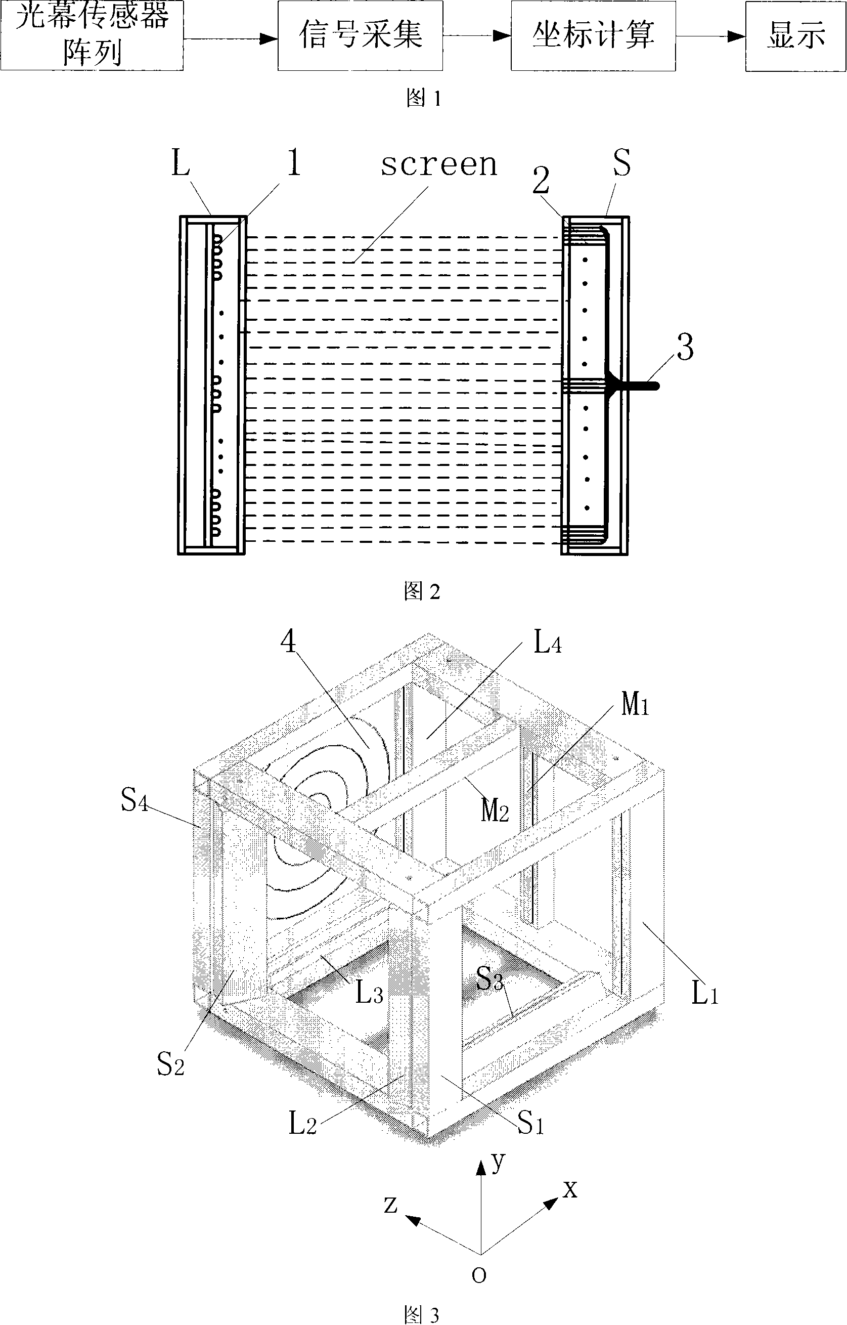
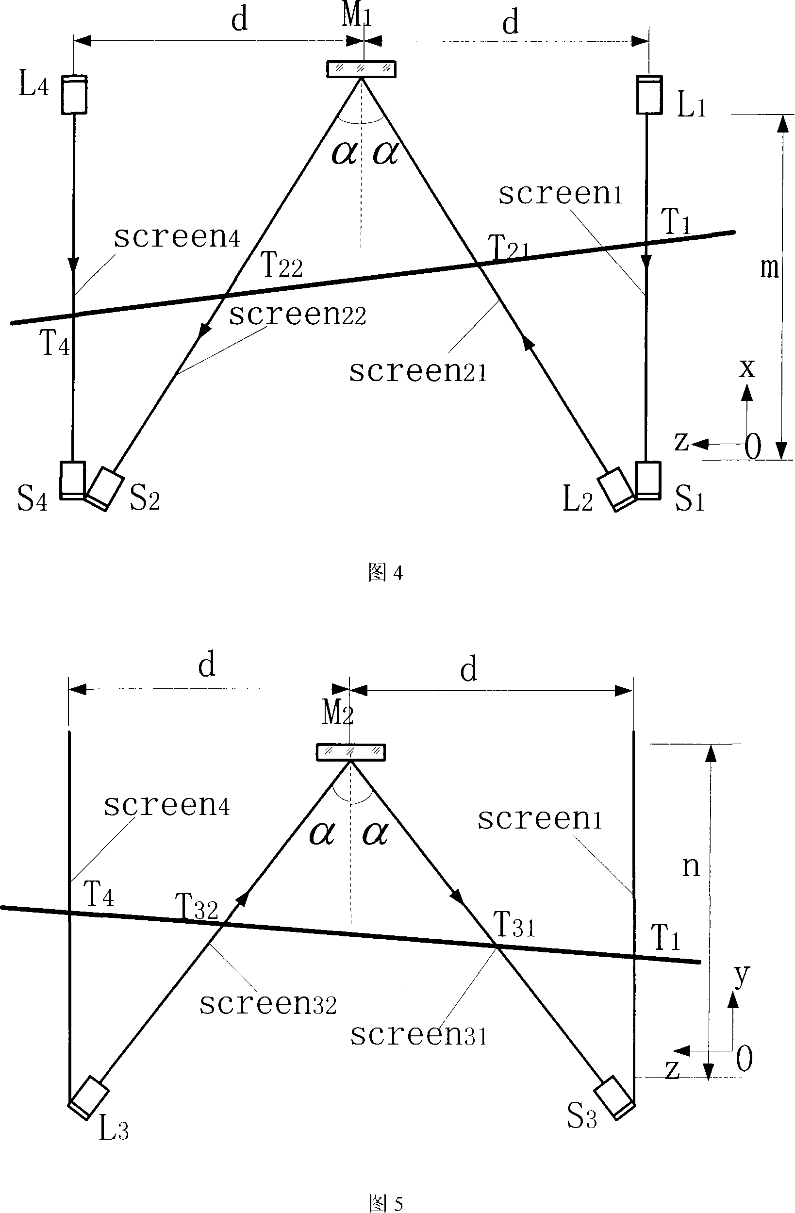
[0030] Embodiment 1: as shown in Figure 1, the realization scheme of the present invention is: light curtain array automatic target reporting device, is made of light curtain sensor, signal acquisition, coordinate calculation and display part, when projectile passes through by light curtain sensor, output The corresponding electrical signal is collected by the signal acquisition device to obtain the time when the projectile passes through the light curtain, and the coordinate calculation part calculates the coordinates of the projectile on the target through the time and the geometric structure parameters of the light curtain, and displays it on the display. The basic unit array of the light curtain sensor in the light curtain array automatic target reporting device of the present invention is composed of a straight line light source L and a corresponding receiving device S. Arrangement composition, the diameter of the optical fiber 2 in this example is 0.8mm, the end face of t...

Embodiment 2

[0031] Embodiment 2: The overall composition and specific scheme are the same as Embodiment 1, see Figure 2, wherein the lengths of the light source L and the receiving device S can be designed according to the usage conditions, and the specific dimensions are determined by the accuracy required by the test. In this example, the length of the light source L and the receiving device S is 1000 mm, and the optical fiber 2 is an optical fiber with a diameter of 1 mm.

Embodiment 3

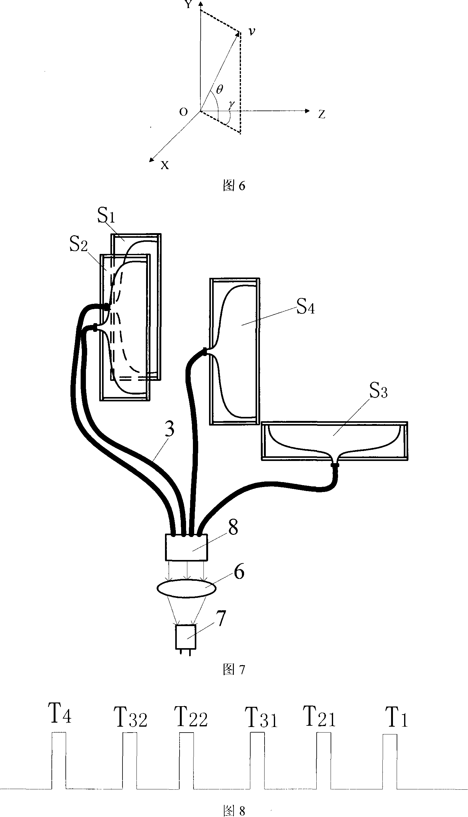
[0032] Embodiment 3: The overall composition and specific scheme are the same as Embodiment 1, referring to Fig. 7, the output ends of all receiving devices S1, receiving device S2, receiving device S3, and receiving device S4 in the light curtain sensor are connected together by an optical cable 3, and the total The optical signal output by the receiving device is converged on the photosensitive surface of the photodetector 7 through the lens 6 . One end of the optical cable 3 is connected to the output end of the receiving device S of each light curtain sensor, and the other end is gathered together by the clamping mechanism 8 . When the projectile passes through the light curtain sensor array, the receiving device S 1 , S 2 , S 3 , S 4 The optical cable 3 guides the luminous flux change in each receiving device to the converging lens 6, irradiates the sensitive surface of the photoelectric receiver 7 after converging, and outputs an electric pulse signal after the signal...


PUM

PropertyMeasurementUnit
Diameteraaaaaaaaaa
Lengthaaaaaaaaaa
Diameteraaaaaaaaaa

Abstract

This invention discloses an automatic target-reporting method and system for indoor and outdoor bullet shooting. It includes veiling sensor array, signal collection, coordinates computation and display parts. The basic cell array of the veiling sensor is composed of a linear light source L and corresponding receiving device. The linear light source L is composed of light-emitting diodes that are arranged in line. The receiving device S is formed by the end face of optical fiber. The veiling sensor is three-dimensional frame structure. Two parallel veiling are used together in the X and Y computed coordinate directions. Each of them has two V shaped veiling which form alpha angle with the two parallel veiling. Thus, they form the special veiling sensor array. Only four sets of veiling basic cell arrays can fulfill the three-dimensional no touch measurement of the bullet. It can give the exact location and speed of the bullet on the target. The rate of false reporting rate is low. It will not be interfered by adjacent target.

Description

technical field [0001] The invention belongs to the technical field of an automatic target reporting device and method for bullet shooting, and mainly relates to an automatic target reporting device using light curtain technology, specifically a light curtain array automatic target reporting device and method. Background technique [0002] In the shooting training of shooting entertainment, army, public security department and the competition, the statistical method of shooting performance has artificial target reporting and automatic target reporting. Manual target reporting is the most traditional and primitive method, which has many disadvantages, such as personal subjectivity, difficulty in identifying heavy holes, time-consuming and laborious, and certain dangers. With the advancement of technology, various automatic target reporting technologies continue to emerge. Automatic target reporting overcomes the disadvantages of manual target reporting, but there are still la...

Claims


Application Information

Patent Timeline
IPC IPC(8): F41J5/02
Inventor 倪晋平冯斌杨雷
Owner XIAN TECHNOLOGICAL UNIV
Learn More