Data collection circuit with dual threshold voltage

A circuit and coding circuit technology, applied in electrical components, analog-to-digital converters, analog-to-digital conversion, etc., can solve the problem of single system analog input voltage and coding circuit, reduce the dynamic performance of data acquisition circuit, and multiple jumps of coding circuit And other issues

Inactive Publication Date: 2008-03-26
无锡矽太恒科电子有限公司
View PDF0 Cites 5 Cited by
  • Summary
  • Abstract
  • Description
  • Claims
  • Application Information

AI Technical Summary

Problems solved by technology

Some circuits first use a low offset 4 comparator LM339, a reference voltage and a precision resistor divider network to form a pre-sampling circuit, which converts the analog input signal V IN Divide the bit into 9 value ranges, and then use the 10-4 line priority encoder 74LS147 to output the gain control code of the program-controlled amplifier circuit; some circuits also use the 8-bit parallel output A/D converter AD673 to realize the binning and encoding of analog signals The circuit is realized by CPLD, and its structure is simple, which overcomes the shortcomings of the traditional building block method of com

Method used


Image

  • Data collection circuit with dual threshold voltage
  • Data collection circuit with dual threshold voltage
  • Data collection circuit with dual threshold voltage

Examples


Embodiment Construction

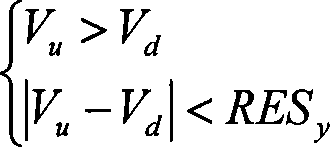
[0015] As shown in Figure 2: one output terminal of the sample-and-hold circuit is connected to the input terminal of the cascaded program-controlled amplifier, the other output terminal is connected to the input terminal of the pre-sampling circuit, and the output terminal of the cascaded program-controlled amplifier is connected to the input of the tail code conversion circuit The output of the tail code conversion circuit is fed back to the encoding circuit, which is fed back to the cascaded program-controlled amplifier after operation by the encoding circuit. The output end of the pre-sampling circuit is connected to the encoding circuit; Connect the program-controlled amplifier with the pre-sampling circuit. First, the pre-sampling circuit performs analog-to-digital conversion on the analog voltage signal and then sends it to the encoding circuit. The encoding circuit controls the amplification factor of the cascaded program-controlled amplifier according to the analog-to-d...


PUM


Abstract

This invention relates to a data collecting circuit, in which, an output end of a sample keeping circuit is connected with the input of a cascade program control amplifier, the other output is connected with the input of a pre-sampling circuit, the output of the cascade program control amplifier is connected with the input of a tail code converting circuit, the output of the pre-sampling circuit is connected with a coding circuit, after the sample keeping circuit collects analog voltage signals, it transfers them to the cascade program control amplifier and the pre-sample circuit, which first of all carries out A/D conversion to the analog voltage signals and then transfers them to the coding circuit to control the amplified multiple of the amplifier, which amplifies the analog signals according to the amplification multiple then to deliver them to the tail code conversion circuit to carry out accurate A/D conversion to it synchronously.

Description

technical field [0001] The invention relates to a data acquisition circuit, in particular to a circuit for high-precision data acquisition. Background technique [0002] The basic schematic diagram of the classic floating-point amplifier is shown in Figure 1. It is mainly composed of a pre-sampling circuit, an encoding circuit and a program-controlled amplifier. First, the encoding circuit sets the amplification factor of the program-controlled amplifier according to the output of the pre-sampling circuit, and then the program-controlled amplifier Send the amplified analog signal to the A / D converter. The floating magnification is called "order code", the A / D conversion result is called "tail code", and the result of the data acquisition system is composed of "order code" + "tail code". This is similar to how floating point numbers are represented in computers, hence the name "floating point" amplifiers. Encoding circuit design is the key technology to realize floating-poi...

Claims


Application Information

Patent Timeline
IPC IPC(8): H03M1/18H03M1/34
Inventor 万振刚
Owner 无锡矽太恒科电子有限公司
Why Eureka
Try Eureka