Strip steel non-roller correcting error method and apparatus

A deviation correction device and strip deviation technology, applied in transportation and packaging, coiling strips, use feedback control, etc., can solve the problems of increased strip scratches, low deviation correction ability, complex system maintenance, etc., to achieve easy Effects of computer control, improved surface quality, and high accuracy of deviation correction

Active Publication Date: 2008-04-02
BAOSHAN IRON & STEEL CO LTD
View PDF2 Cites 27 Cited by
  • Summary
  • Abstract
  • Description
  • Claims
  • Application Information

AI Technical Summary

Problems solved by technology

However, this method has the following disadvantages: (1) The inertia of the correction device is large; (2) The system is complex; (3) The hydraulic system leaks; (4) The system responds slowly
Such as the Chinese patent CN02159175.X, which uses magnetic force and grinding pressure to correct the deviation of the strip. The disadvantages of this patent are: (1) only suitable for magnetic strips; (2) low deviation correction ability
This method is more suitable for thin strips, and due to the compression of the grinding wheel, the tension distribution of the cross-section of the strip is uneven, and the surface of the strip will have indentation defects along the running direction.
[0007] The above three correction methods are all contact correction methods. In addition to slow response speed and complicated system maintenance, the contact correction method also increases the chance of strip scratches and other surface defects due to the introduction of correction rollers.

Method used


Image

  • Strip steel non-roller correcting error method and apparatus
  • Strip steel non-roller correcting error method and apparatus

Examples


Embodiment 1

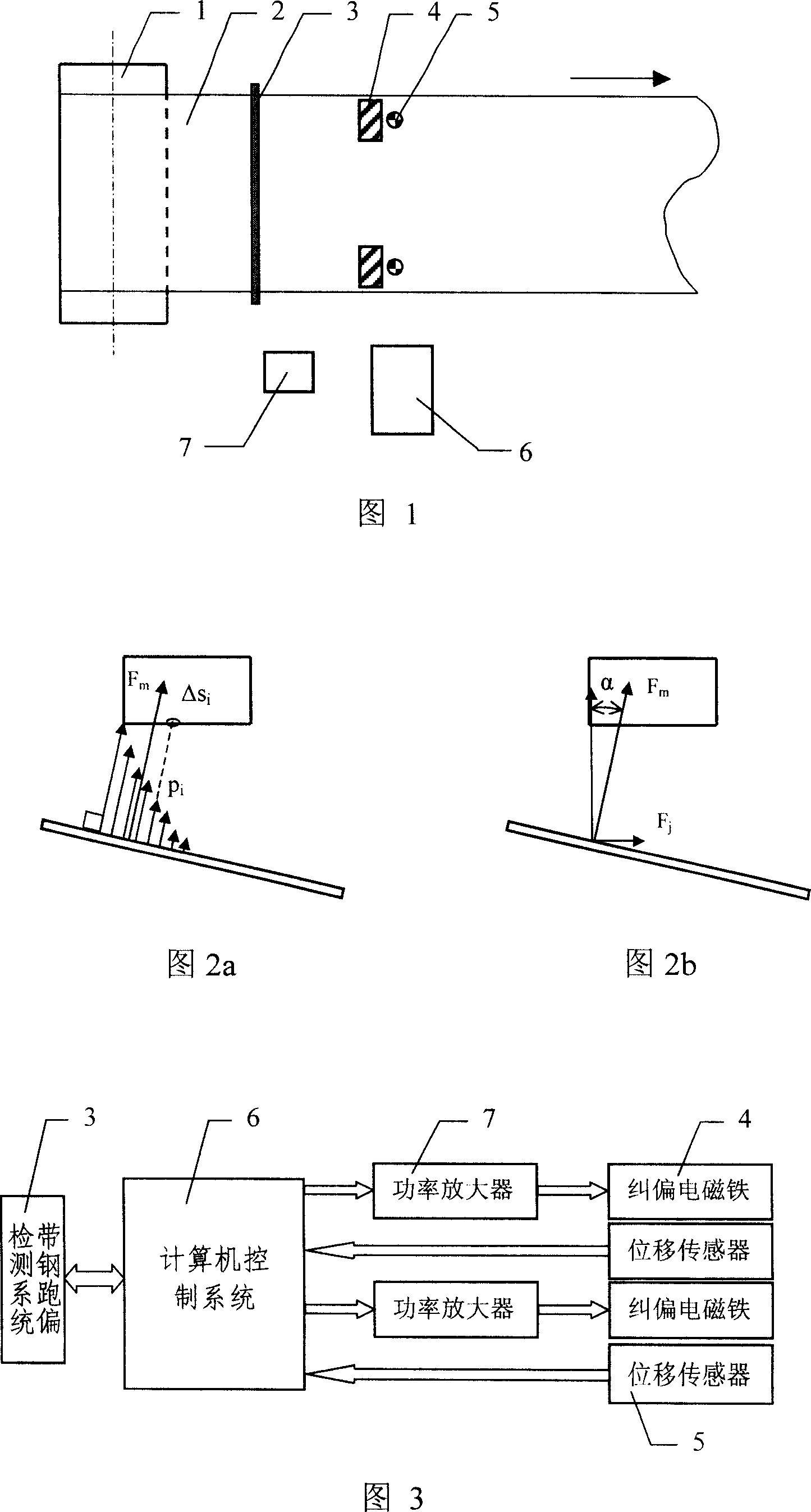
[0041] Referring to Fig. 4, for a strip steel 2 with a width of 1400mm, a pair of rectifying electromagnets 4 with a bottom surface size of 150mm×150mm are symmetrically arranged on both sides of the running center line of the strip steel 2, and the outer distance between the two electromagnets 4 is 1300mm . When there is no excitation current, the vertical distance from the bottom surface of the electromagnet 4 to the surface of the strip steel 2 is 30 mm. An eddy current displacement sensor 5 is arranged at the center of each electromagnet 4 to measure and control the distance from the electromagnet 4 to the steel strip 2 .

[0042] The area of ​​the electromagnet 4 facing the strip steel 2 should be as large as possible, so that on the one hand, a larger electromagnetic correction force can be obtained; Detrimental effects of force concentration on strip 2 surface shape and other surface qualities. After testing, the deviation correction control accuracy can reach ±1mm, o...

Embodiment 2

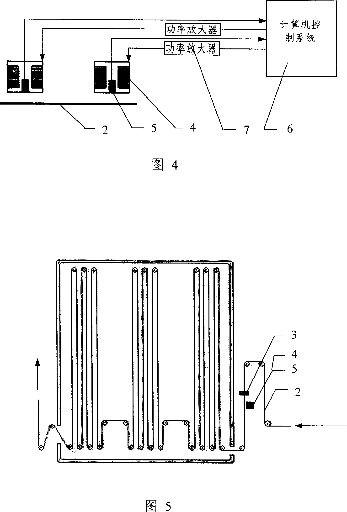
[0044] Referring to Fig. 5, before the continuous annealing processing production line (CAPL) steel strip enters the looper, the deviation of the strip steel is corrected by using a roller-less correction method.


PUM


Abstract

The present invention relates to a strip steel correcting technology, in particular to relate to a non-contacting strip steel correcting technology method and a device. A no-roll strip steel correcting technology is characterized in that a couple of electromagnets are arranged above two sides of the strip steel in a place where the strip steel is easy to deviate or has requirements to the deviating quantity. When a strip steel deviating quantity detecting system detects the deviation of the strip steel, a detected signal is changed into an electric signal; the deviating quantity and deviating direction is gained by gathering and operating the electric signal through a computer; the clearance between the strip steel and the electromagnet is changed by controlling an excitation current of two electromagnets; then the deviation of the strip steel is corrected. At the same time, the distance between the electromagnet and the strip steel is detected by a displacement sensor; then the detected signal is input into a computer controlling system; the excitation current of the electromagnet is controlled by the output signal made by the computer controlling system after operating. The present is simple in structure, high in response rate, precise in deviation correcting and easy to realize the computer controlling.

Description

(1) Technical field [0001] The invention relates to a strip steel deviation correction technology, in particular to a non-contact strip steel deviation correction method and device. (2) Background technology [0002] In modern continuous strip steel production, due to equipment installation, strip shape and other reasons, the high-speed running strip steel will have deviation phenomenon, which will cause scratches on the strip steel surface, reduce the product quality, and even Cause production and equipment accidents such as broken belts, reduce labor productivity, and increase troubleshooting time and costs. Therefore, it is necessary to install a strip deviation correction device on the strip steel production line. [0003] There are three types of automatic deviation correction methods for existing strip production lines: [0004] Electro-hydraulic servo correction method. The method is to install the deviation correction roller on a floating frame, and the electro-hy...

Claims


Application Information

Patent Timeline
Patent Type & Authority Applications(China)
IPC IPC(8): B65H23/032B65H26/00G05D3/20
Inventor 王泽济张永杰
Owner BAOSHAN IRON & STEEL CO LTD
Why Eureka
Try Eureka