Image display system and method for driving display component

A technology for image display and display components, applied to static indicators, instruments, etc., which can solve problems such as floating nodes with unclear voltage levels, coupling noise, gate voltage signal distortion of NMOS transistor 22, etc.

Inactive Publication Date: 2008-04-02
INNOLUX CORP
View PDF0 Cites 8 Cited by
  • Summary
  • Abstract
  • Description
  • Claims
  • Application Information

AI Technical Summary

Problems solved by technology

Similarly, if the threshold voltage Vtn of the NMOS transistor 27 is also reduced, some leakage current will be caused to further reduce the gate voltage level of the NMOS transistor 28
When the gate voltage of the NMOS transistor 28 drops to a low voltage level, the gate of the NMOS transistor 22 may generate floating nodes (floating nodes) with unclear voltage levels, such as nodes

Method used


Image

  • Image display system and method for driving display component
  • Image display system and method for driving display component
  • Image display system and method for driving display component

Examples


Embodiment Construction

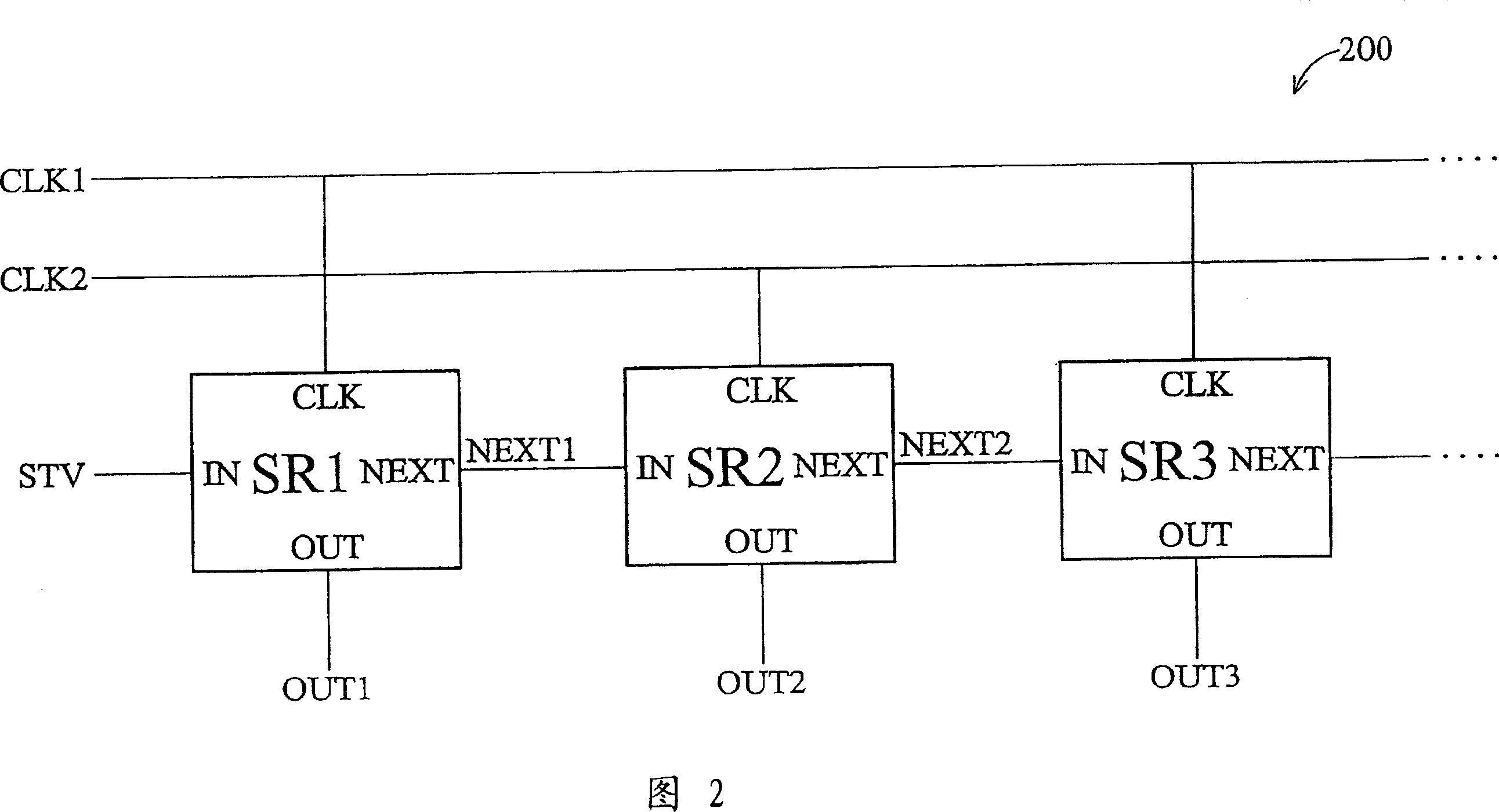
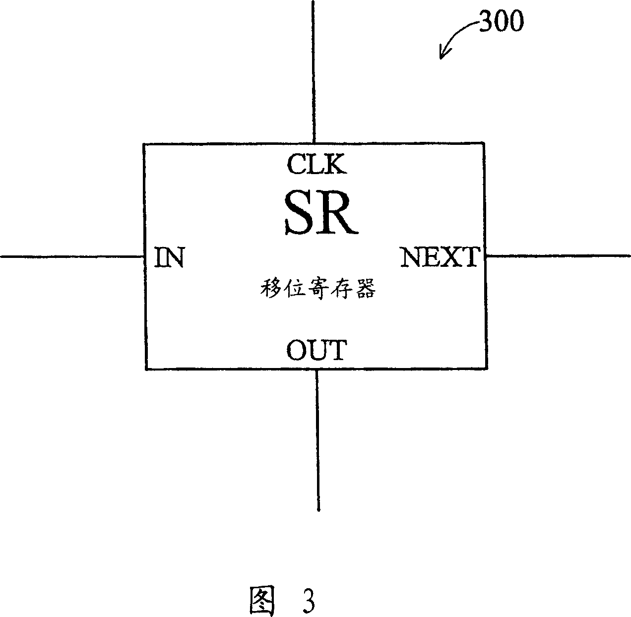
[0033]FIG. 2 is a schematic diagram of a signal driving circuit according to an embodiment of the present invention. The signal driving circuit 200 includes three serially connected shift registers: a first shift register SR1 , a second shift register SR2 and a third shift register SR3 . The first shift register SR1 and the third shift register SR3 receive a first clock signal CLK1, and the second shift register SR2 receives a second clock signal CLK2. Wherein, the first clock signal CLK1 and the second clock signal CLK2 are two clock signals with a phase difference, and the period of the output signal has a specific duty cycle. Each shift register has a clock input terminal CLK, an input terminal IN, an output terminal OUT and a driving terminal NEXT, as shown in FIG. 3 . FIG. 3 is a schematic diagram of one stage of the shift register 300 in FIG. 2 . The clock input terminal CLK is used to receive a clock signal CLKx, the input terminal IN receives a start pulse signal, th...


PUM


Abstract

The invention provides an image display system which comprises a signal drive circuit, wherein, the signal drive circuit comprises a plurality of tandem shift registers which are controlled by a first clock signal and a second clock signal to generate corresponding drive signal in turn according to a start pulse signal; each shift register comprises a first clock input end, an input end, an output end and a drive end; the first clock input end is used to receive one of the first clock signal and the second clock signal; the input end receives a first pulse signal; the output end generates an output signal; the drive end generates a drive signal according to the received clock signal to drive a sublevel shift register; moreover, the output signal and the drive signal are generated at different time intervals.

Description

technical field [0001] The invention relates to a signal driving circuit and method, in particular to a signal driving circuit in an image display system and a method for driving a display component. Background technique [0002] A display panel in an image display system, such as a TFT-LCD panel, usually includes a display component, and the display component has a two-dimensional pixel array with a plurality of pixels. These pixels can be controlled by a plurality of data lines and a plurality of gate signal lines. A driving circuit composed of several shift registers (SR) connected in series is used to provide corresponding driving signals so that the gate signal lines can be activated sequentially. [0003] Generally speaking, each shift register (SR) includes an input terminal, an output terminal, a power supply terminal and several clock signal terminals. An output terminal of the shift register is connected to one gate signal line of the LCD array, and each gate sig...

Claims


Application Information

Patent Timeline
IPC IPC(8): G09G3/36G09G3/20G02F1/133
Inventor 黄圣峰
Owner INNOLUX CORP
Why Eureka
Try Eureka