Thin film transistor display device and method of manufacturing the same
A technology of thin-film transistors and display devices, which is applied in the field of semi-transmissive and semi-reflective liquid crystal displays and their manufacturing, and can solve problems affecting product qualification rate, particle pollution, multi-hour cost, labor cost and machine purchase cost, etc.
- Summary
- Abstract
- Description
- Claims
- Application Information
AI Technical Summary
Problems solved by technology
Method used
Image
Examples
Embodiment 1
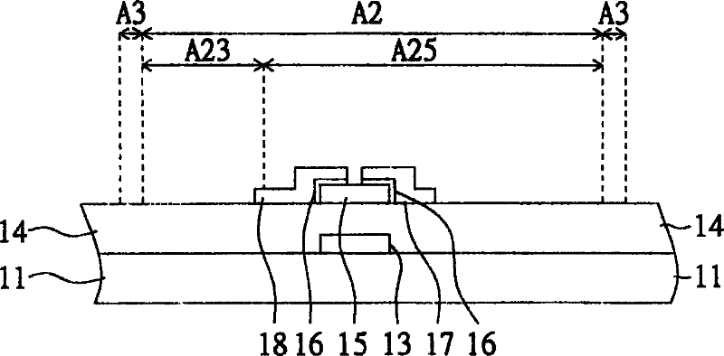
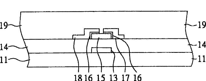
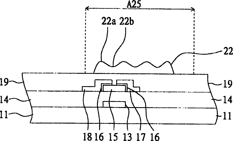
[0016] Embodiment 1 of the present invention uses a half-tone photomask to define the electrodes in the light-transmitting region and the electrodes in the reflecting region, so that the number of photomasks in the manufacturing process is reduced. Figure 1A-1L A flowchart showing a manufacturing method of a TFT display device of a transflective display according to Embodiment 1 of the present invention. The TFT display device of the transflective display in this embodiment has a pixel area A2 composed of a light-transmitting area A23 and a reflecting area A25. The thin film transistor display device also has a pixel interval area A3, which surrounds the light-transmitting area A23 and the reflecting area A25.
[0017] First, if Figure 1A As shown, a gate electrode 13, a gate insulating layer 14, a channel layer 15, a heavily doped ohmic contact layer 16, a source metal layer 17 and a drain metal layer are formed. 18 on the substrate 11. Wherein, the source metal layer 17 ...
Embodiment 2
[0023]In the second embodiment of the present invention, a half-tone photomask is used to define the via hole and the electrode in the reflective region. In terms of operation steps, the difference between the manufacturing method of the thin film transistor display device of this embodiment and the manufacturing method of the thin film transistor display device of the first embodiment lies in the step after forming the passivation layer, and the difference of the structure of the thin film transistor display device is that The structure of the via hole and the reflective area, and the rest of the same structure will not be repeated.
[0024] Please refer to Figure 2A-2J A flowchart showing a manufacturing method of a TFT display device of a transflective display according to Embodiment 2 of the present invention. First, if Figure 2A As shown, the gate 13, the gate insulating layer 14, the channel layer 15, the heavily doped ohmic contact layer 16, the source metal layer 1...
Embodiment 3
[0029] In the third embodiment of the present invention, a half-tone photomask is used to define the via hole and the electrode in the reflective region. The manufacturing method of the thin film transistor display device of this embodiment is different from the manufacturing method of the thin film transistor display device of the second embodiment in the step after coating the photoresist, and the structure of the thin film transistor display device is different in the structure of the reflective region, The rest of the similarities will not be repeated.
[0030] Please refer to Figure 3A ~ 3I A flowchart showing a manufacturing method of a thin film transistor display device of a transflective display according to Embodiment 3 of the present invention. First, if Figure 3A As shown, the gate 13, the gate insulating layer 14, the channel layer 15, the heavily doped ohmic contact layer 16, the source metal layer 17 and the drain metal layer 18, and the passivation layer ar...
PUM
 Abstract
Description
Claims
Application Information
 - R&D
- Intellectual Property
- Life Sciences
- Materials
- Tech Scout
- Unparalleled Data Quality
- Higher Quality Content
- 60% Fewer Hallucinations
Browse by: Latest US Patents, China's latest patents, Technical Efficacy Thesaurus, Application Domain, Technology Topic, Popular Technical Reports.
© 2025 PatSnap. All rights reserved.Legal|Privacy policy|Modern Slavery Act Transparency Statement|Sitemap|About US| Contact US: help@patsnap.com


