Laser source device, image display device and monitor device having the same

A technology of laser light source and light source, which is applied to lasers, laser parts, phonon exciters, etc., can solve the problems of fundamental wave laser light source power reduction, little improvement in light utilization efficiency, and no improvement in light utilization efficiency, etc. High degree of freedom, easy control, and consistent polarization direction

Inactive Publication Date: 2008-04-02
SEIKO EPSON CORP
View PDF1 Cites 5 Cited by
  • Summary
  • Abstract
  • Description
  • Claims
  • Application Information

AI Technical Summary

Problems solved by technology

And, if such residual fundamental wave light is directly returned to the fundamental wave laser light source, the power of the fundamental wave laser light source may be reduced and become unstable, so it is necessary not to return the remaining fundamental wave light to the light source.
Therefore, it is possible to increase the size of the optical system
In addition, since the length of the optical path becomes longer and the number of passes through optical elements increases, light loss may also occur
[0007] Furthermore, in the laser light source device described in Patent Document 1, in order to combine the first SHG light and the second SHG light, the polarization directions are in a state different from each other by 90°, so the output light has two types of polarization. Combining light, therefore, in the case where the laser light source device described in Patent Document 1 is considered to be used in combination with a polarization control device (such as a liquid crystal device) that can only use one type of polarized light, if If there is no configuration for aligning the polarization directions of the first SHG light and the second SHG light, only one SHG light can be used
[0008] That is, in the laser light source device described in Patent Document 1, although the power drop of the output light can be suppressed to some extent, and a stable output can be obtained, the utilization efficiency of the light has not been greatly improved.
In particular, when used in combination with a polarization-controlling device, there is a possibility that the utilization efficiency of light may not be improved at all.

Method used


Image

  • Laser source device, image display device and monitor device having the same
  • Laser source device, image display device and monitor device having the same
  • Laser source device, image display device and monitor device having the same

Examples


no. 1 Embodiment approach

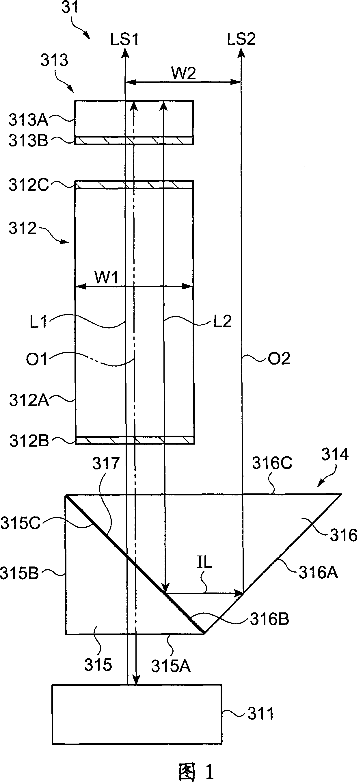
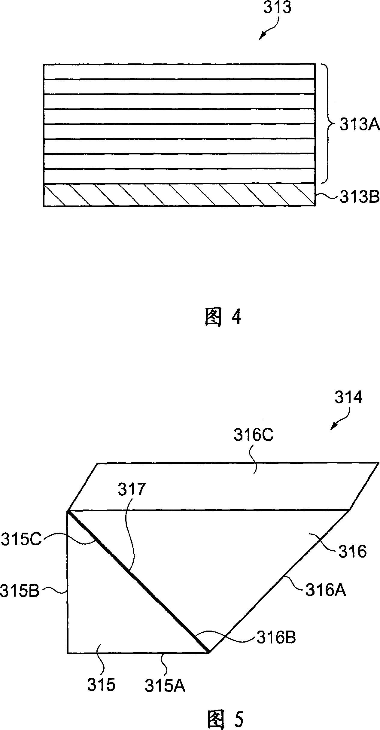
[0048] FIG. 1 is a schematic diagram showing a schematic configuration of a laser light source device in a first embodiment. The laser light source device 31 includes a light source 311 , a wavelength conversion element 312 , an external resonator 313 , and an optical path conversion element 314 . The light source 311 emits light of the first wavelength.

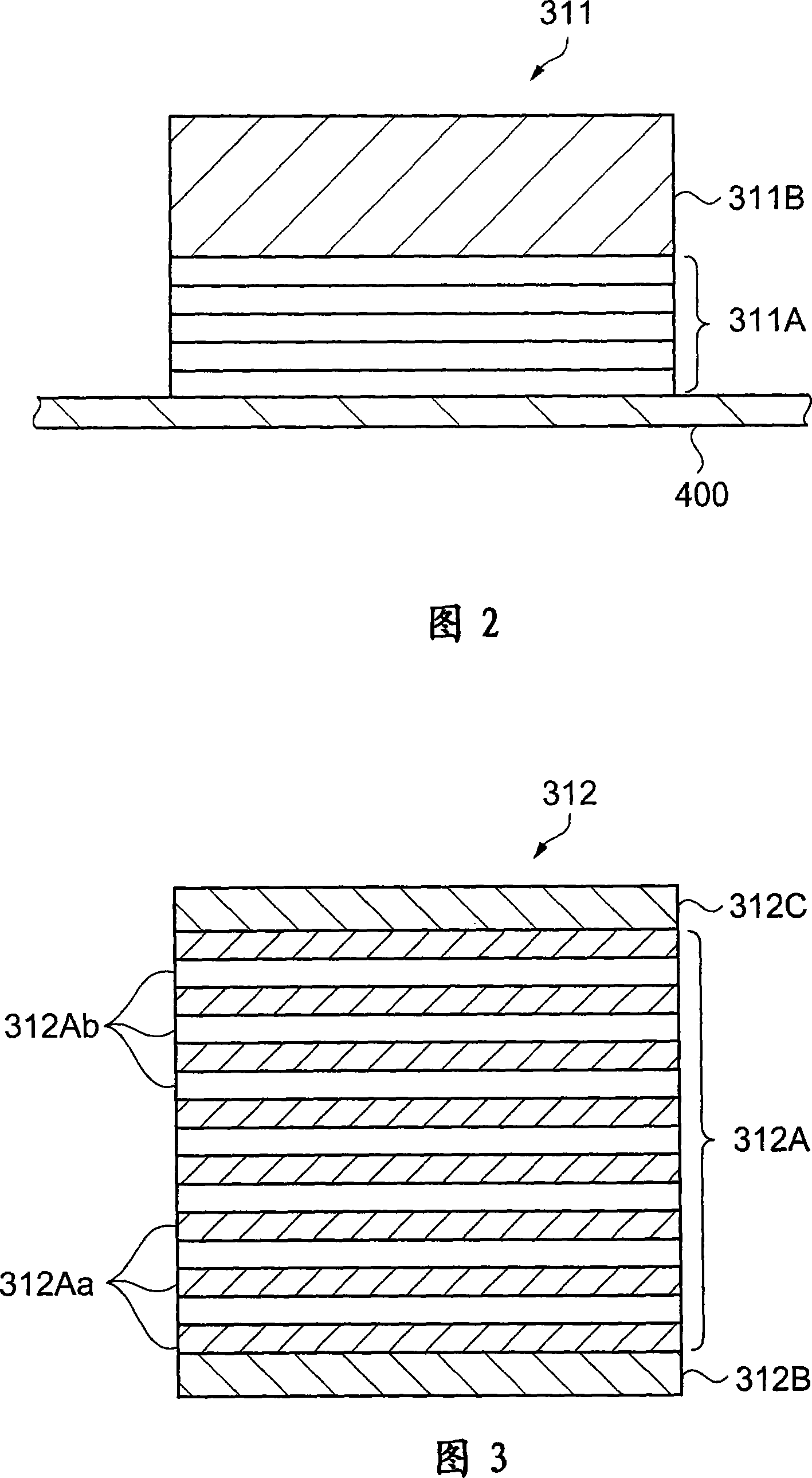
[0049] FIG. 2 is a cross-sectional view schematically showing the structure of the light source 311 . The light source 311 shown in FIG. 2 is a so-called surface-emitting semiconductor laser, and has: a substrate 400 made of, for example, a semiconductor wafer, a mirror layer 311A ​​formed on the substrate 400 and having a function as a reflection mirror, and laminated on the substrate 400. The laser medium 311B on the surface of the mirror layer 311A.

[0050] The mirror layer 311A ​​is formed on the substrate 400 by, for example, a laminate of a high-refractive-index dielectric and a low-refractive-index dielectric forme...

no. 2 approach

[0098] FIG. 6 is a schematic diagram showing a schematic configuration of a laser light source device 41 in the second embodiment. The laser light source device 41 of the second embodiment differs from the laser light source device 31 of the first embodiment only in the configuration of the optical path conversion element 414, and is the same as that of the first embodiment other than that. Therefore, in FIG. 6 , the same members as those in the first embodiment are given the same reference numerals, and descriptions thereof are omitted or simplified. Furthermore, the same applies to the process up to obtaining output light from the laser light source device 41 , and its detailed description is also omitted or simplified.

[0099] In the laser light source device 41 shown in FIG. 6 , the optical path conversion element 414 includes a plate-shaped member 414A as a translucent member, a selective reflection film 317 , and a reflection film 416 . The plate member 414A is made of...

no. 3 approach

[0113] FIG. 7 is a schematic diagram showing a schematic configuration of a laser light source device in a third embodiment. The laser light source device 51 of the third embodiment differs from the laser light source device 31 of the first embodiment only in the configuration of the optical path conversion element 514, and is the same as the first embodiment described above except for that. Therefore, the same reference numerals are assigned to the same components as those in the first embodiment, and descriptions thereof will be omitted or simplified. Furthermore, the same applies to the process up to obtaining output light from the laser light source device 51 , and its detailed description is also omitted or simplified.

[0114] In the laser light source device 51 shown in FIG. 7 , an optical path conversion element 514 includes a prism 515 as a translucent member, and a selective reflection film 317 . The prism 515 is made of optical glass such as BK7 and has the shape o...


PUM


Abstract

A laser light source device capable of high effectively restraining output light power decreasing, high light using rate, consistent polarization direction of the output light, and outputting stably, and an image display device with the laser light source device and a monitor device are provided in the present invention. The laser light source device (31) has: a light source (311), a wavelength changing element (312), an external resonance device (313) and a light changing element (314). The wavelength changing element (312) is arranged in the resonance structure, the second laser (LS2) is broken out according with a second light path (02) by the light path changing element (314), towards the approximately same direction with a first laser (LS1) advancing direction, it together with the first laser (LS1) are used as output light. Selective reflecting film (317) and reflecting face (316A) for taking out the second laser (LS2) are integrated by prisms (315, 316).

Description

technical field [0001] The present invention relates to a laser light source device that emits laser light, and an image display device and a monitor device including the laser light source device. Background technique [0002] In recent years, laser light source devices have been widely used in optoelectronic fields such as optical communication, optical application measurement, and optical display. [0003] As such a laser light source device, there are those that directly use the wavelength of the fundamental laser beam, and those that convert and use the wavelength of the fundamental laser beam. In the latter laser light source device, a second harmonic light generation (SHG: Second Harmonic Generation) element is known as an element that converts the wavelength of the fundamental laser beam. [0004] Here, since the conversion efficiency of the SHG is generally about 30 to 40%, the power of the light converted by the SHG element is considerably smaller than the power o...

Claims


Application Information

Patent Timeline
Patent Type & Authority Applications(China)
IPC IPC(8): H01S3/00G02F1/00G02F1/35
Inventor 熊谷惠子今村峰宏
Owner SEIKO EPSON CORP
Why Eureka
Try Eureka