Micro-channel single phase convection and capillary groove phase inversion heat combined cooling method and device

A technology of phase change heat and cooling method, applied in the cooling of instruments, cooling/ventilation/heating renovation, instruments, etc., can solve the problems of large total heat dissipation capacity, high heat dissipation heat flow density, small heat dissipation area, etc., to achieve good cooling The effect of heat dissipation, high strength and high convection heat transfer coefficient

Inactive Publication Date: 2008-04-02
INST OF ENGINEERING THERMOPHYSICS - CHINESE ACAD OF SCI
View PDF0 Cites 4 Cited by
  • Summary
  • Abstract
  • Description
  • Claims
  • Application Information

AI Technical Summary

Problems solved by technology

[0003] The purpose of the present invention is to overcome the technical defects that the existing air-cooled and water-cooled heat dissipation technologies require a large heat dissipation area and insufficient heat dissipation capacity, and pr

Method used


Image

  • Micro-channel single phase convection and capillary groove phase inversion heat combined cooling method and device
  • Micro-channel single phase convection and capillary groove phase inversion heat combined cooling method and device

Examples


Embodiment 1

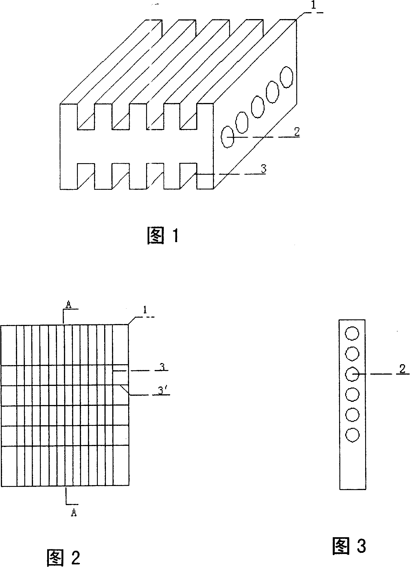
[0023] Embodiment 1: see Fig. 1, a lot of circular microchannels 2 are set inside metal plate or other heat-conducting materials 1, form microchannel group, and many rectangular capillary microgrooves 3 are set on the outer surface, form capillary microgroove group, this band A heat exchange structure with microchannels and capillary grooves is called a heat sink. As shown in Fig. 1 and Fig. 3, the microchannels 2 are densely arranged horizontally inside the heat-conducting material 1, and as shown in Fig. 1 and Fig. 2, the capillary microgrooves 3 are densely arranged longitudinally. The diameter of the microchannel 2 is in the range of 0.05-1mm, the distance between the microchannels is in the range of 0.05-5mm, the length of each microchannel is in the range of 5-50mm, and the cross-section of the microchannel is circular, and the capillary microgroove 3 The channel is a rectangular micro channel, its width and channel depth are in the range of 0.05-2mm, and the distance be...

Embodiment 2

[0025] Embodiment 2: As shown in Fig. 2, the heat sink of this embodiment has a plurality of capillary microgrooves 3 densely arranged vertically, and a plurality of transverse capillary microgrooves 3' are arranged crosswise on the densely arranged longitudinal capillary microgrooves 3. The capillary microchannels 3' arranged horizontally can ensure the capillary driving force of the liquid working medium flowing along the longitudinal capillary microchannels 3 under ultra-high heat load, so that the liquid working medium evaporated in the heated area can be replenished in time, thereby improving the cooling efficiency. In this embodiment, the groove width of the capillary micro-channel 3 is 0.2mm, the groove depth is 0.5mm, and the groove spacing is 0.2mm, and the groove width of the transverse capillary micro-channel 3' is 0.4mm, the groove depth is 0.8mm, and the groove spacing is 5mm.

Embodiment 3

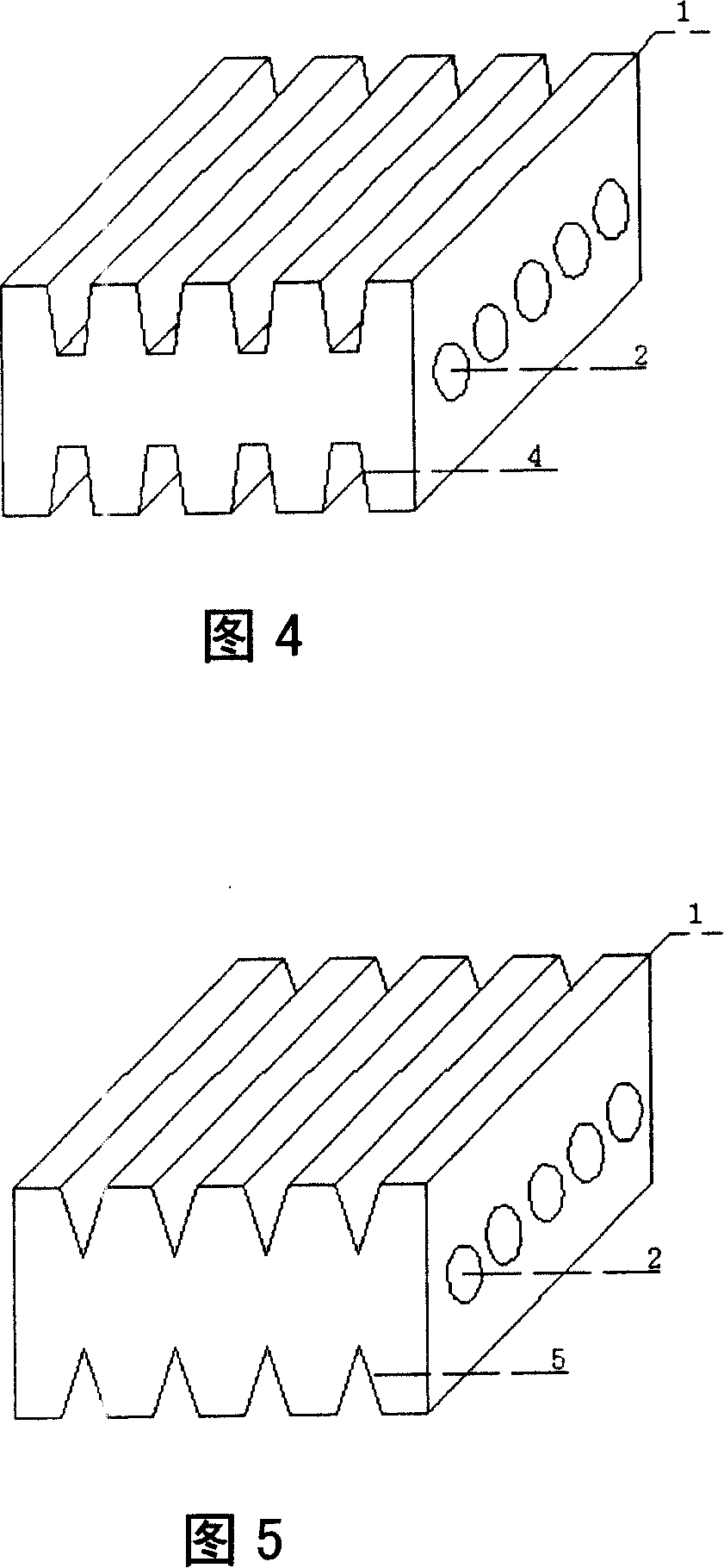
[0026] Embodiment 3: See Fig. 4, the plurality of capillary grooves 4 of the heat sink of this embodiment are vertically densely arranged, and its cross section is trapezoidal, the length of the upper base of the trapezoid is 0.2 mm, the length of the lower base is 0.4 mm, and the groove depth is 0.8mm, the spacing is 0.2mm.


PUM

PropertyMeasurementUnit
Boiling pointaaaaaaaaaa
Diameteraaaaaaaaaa

Abstract

The invention, relates to a cooling method, using the combination of micorchannel single-phase convection and remoteness groove phase transforming heat, and a device thereof, special components and a method of heat dissipation. The process is: high boiling point working liquid flows through the surface of a heating body, enters a plurality of micor-channels arranged inside heat conducting material after absorping heat; another low boiling point liquid in the remoteness grooves is inhaled by the capillary force produced by a plurality of remoteness grooves arranged on the outer surface of heat conducting material; heat is transferred by the high boiling working liquid in the micro-channels through heat exchanging of high intensity microscale singlephase convection to heat conducting material. The heat of a heating body is taken away by another low boiling point working liquid, which generates evaporation and boiling of high intensity when the working liquid is heated, in the remoteness grooves arranged on outer surface of heat conducting material. The heat exchanging element of remoteness grooves arranged on outer surface of heat conducting material has micro-channels inside is special device of the invention.

Description

Technical field: [0001] The invention relates to a heat radiation cooling method, in particular to a cooling method and a device for high-power electronic and optoelectronic devices. Background technique: [0002] At present, there are mainly two ways to cool high-power electronic and optoelectronic devices: one is to use heat sinks combined with fans for air cooling. Thermal silica gel (silicone grease) is used to reduce the thermal resistance of heat conduction, and the fan is placed on the end face of the heat dissipation fin to use the principle of convection heat transfer to dissipate heat to the environment through the surface of the fin to ensure that the device works within the normal operating temperature range. The main defect of this technology is: as the power of electronic and optoelectronic devices increases, the greater the heat dissipation required to maintain normal operating temperature, the greater the power consumption of the fan, and the greater the heat...

Claims


Application Information

Patent Timeline
IPC IPC(8): H05K7/20G12B15/06
Inventor 胡学功王涛唐大伟
Owner INST OF ENGINEERING THERMOPHYSICS - CHINESE ACAD OF SCI
Why Eureka
Try Eureka