Thread drawing device of sewing machine

A sewing machine and thread puller technology, applied in the field of sewing machines, can solve the problems of difficult assembly and maintenance, low working stability, complex overall structure, etc., and achieve the effects of low manufacturing cost, beautiful stitches, and simple overall structure

Inactive Publication Date: 2008-04-09
JACK SEWING MASCH CO LTD
View PDF2 Cites 13 Cited by
  • Summary
  • Abstract
  • Description
  • Claims
  • Application Information

AI Technical Summary

Problems solved by technology

However, due to the complex overall structure of the device, the high manufacturing cost, and the difficulty in assembly and daily mainten

Method used


Image

  • Thread drawing device of sewing machine
  • Thread drawing device of sewing machine
  • Thread drawing device of sewing machine

Examples


Embodiment 1

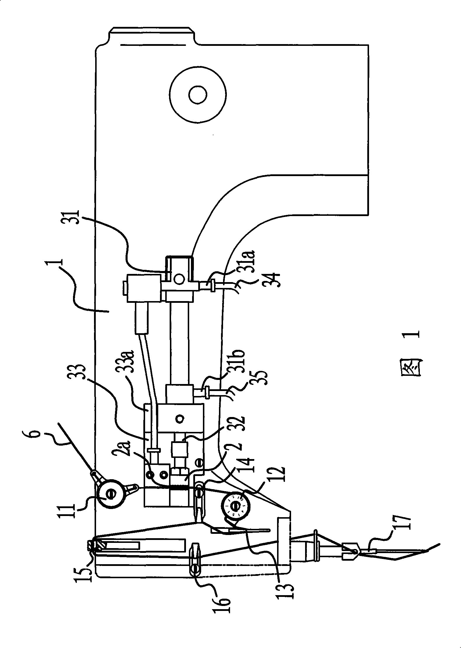
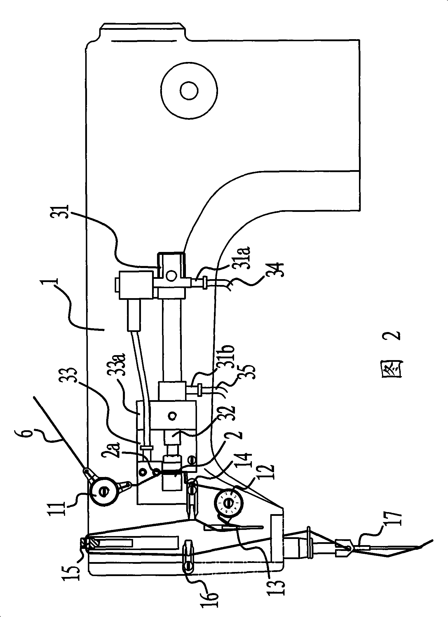
[0028] As shown in Figures 1 and 2, the machine head 1 of the sewing machine is provided with a small thread clamp nut 11, a thread clamp 12, a slow thread hook 13, a right thread 14, and a thread take-up lever 15 for the suture 6 to pass through in sequence. , and cross thread 16 to the left, and finally reach machine needle 17. The thread puller of the sewing machine is arranged on the machine head 1 of the sewing machine, and is located between the small thread clamping nut 11 and the thread clamping device 12 . The wire puller is composed of a wire pull head 2 arranged on the machine head 1 and a driving device that makes the wire pull head 2 slide back and forth in the horizontal direction. After the suture 6 comes out from the small thread clamp nut 11, it leads to the thread clamp 12 through the thread pulling head 2.

[0029] The driving device includes an air cylinder 31 fixed on the machine head 1 , and a wire drawing head 2 fixed on the top end of a piston rod 32 o...

Embodiment 2

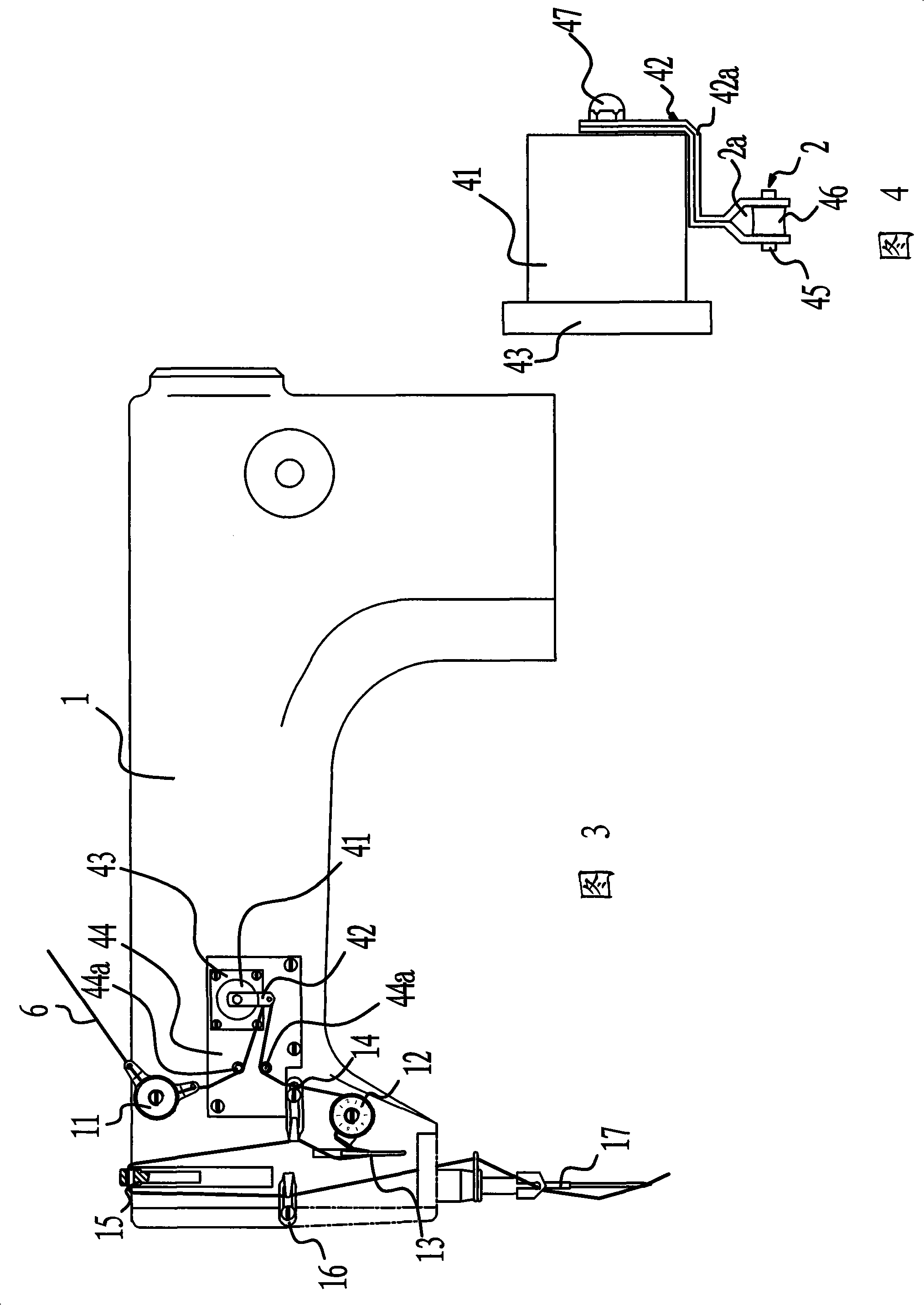
[0035] As shown in Figure 3, in the present embodiment, the driving device includes a stepper motor 41 fixed on the machine head 1, the motor shaft of the stepper motor 41 is fixedly connected with one end of the fork 42, and the above-mentioned pull head 2 is provided with At the other end of the swing rod 42.

[0036] More specifically, the stepping motor 41 is fixed on the seat plate 43 by screws, and the seat plate 43 is fixed on the side of the machine head 1 by a support plate 44 . The support plate 44 is fixedly connected with the machine head 1 by screws. As shown in FIG. 4 , the swing rod 42 in this embodiment is bent into a Z shape by two side-by-side rods 42a, one end of which is fixedly connected to the motor shaft through a nut 47, and the other end is bifurcated to form a fork. The fork 42 is buckled on the periphery of the stepper motor 41 . A bearing pin 45 is installed on the fork, and a roller 46 for suture bypassing is sleeved on the bearing pin 45 . A pi...

Embodiment 3

[0041] As shown in FIG. 5 , in this embodiment, the driving device includes an electromagnet 51 fixed on the machine head 1 , and the above-mentioned wire pulling head 2 is fixed on the top end of the armature rod 52 of the electromagnet 51 . More specifically, the electromagnet 51 is fixed on the machine head 1 through a mounting plate 53, and the mounting plate 53 and the machine head 1 are fixedly connected by screws. The pull head 2 is a slider that can slide back and forth on the mounting plate 53 in the horizontal direction. In order to make the sliding smoother and more stable, the support frame 33 and the pull head 2 can be connected by slide rails.

[0042] The working process of this embodiment is as follows:

[0043] When the sewing machine was working normally, this wire puller was not working, and the wire puller 2 was positioned between the small thread clamp nut 11 and the thread clamp 12, and the suture 6 between the two was not bent. When the sewing machine ...


PUM


Abstract

The invention provides a wire grip of a sewing machine, pertaining to the sewing machine field, which solves the problem that: an ordinary computer controlled flat bed sewing machine tends to cause a nest-shaped stitch. The wire grip of the sewing machine is positioned on a machine head of the sewing machine and between a small wire clamping nut and a wire clamping device; the wire grip consists of a wire drawing head arranged on the machine head and a drive device that can ensure the wire drawing head to slide to and fro along the level direction, and the wire drawing head is provided with a through hole for passing a sewing wire. The wire grip of the sewing machine has the advantages that the nest shaped stitch does not be produced during the sewing process, so the stitch is beautiful; moreover, the wire grip has the advantages of simple whole structure, convenient operation and using, low manufacturing cost, and good working stability.

Description

technical field [0001] The invention relates to the field of sewing machines, in particular to a thread puller capable of pulling back excessively long thread ends so as to make the stitches beautiful when the sewing machine is started. Background technique [0002] Ordinary computerized lockstitch sewing machines generally have stitches tangled into balls when they are started, forming a group of nest-like stitches on the fabric, which affects the beauty and sewing quality of the stitched fabric. The reason for this phenomenon is: after the automatic thread trimming when the computerized sewing machine was stopped last time, the thread end remained in the needle hole for too long; For barbed cloth, the excessively long thread will be left under the fabric; in the next sewing process, this excessively long thread will form a bird's nest-like stitch on the fabric. [0003] In order to solve the problems referred to above, people have invented various thread cutting devices, ...

Claims


Application Information

Patent Timeline
IPC IPC(8): D05B47/00D05B51/00D05B53/00D05B65/06
Inventor 阮积祥
Owner JACK SEWING MASCH CO LTD
Why Eureka
Try Eureka