

Method of implementing high-isolation low-insertion loss RF switch
A radio frequency switch, high isolation technology, applied in the field of radio frequency switch circuits or integrated circuits, which can solve the problems of complex technology and narrow operating frequency band
- Summary
- Abstract
- Description
- Claims
- Application Information
AI Technical Summary
Problems solved by technology
Method used
Image

Examples
Embodiment Construction
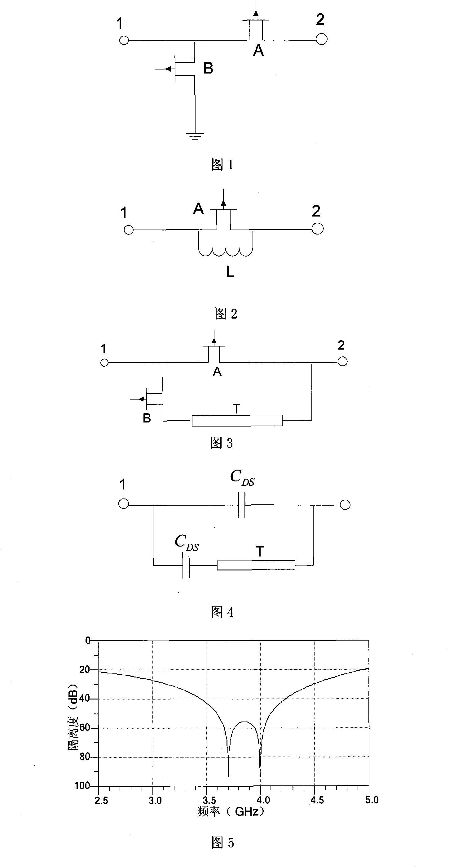
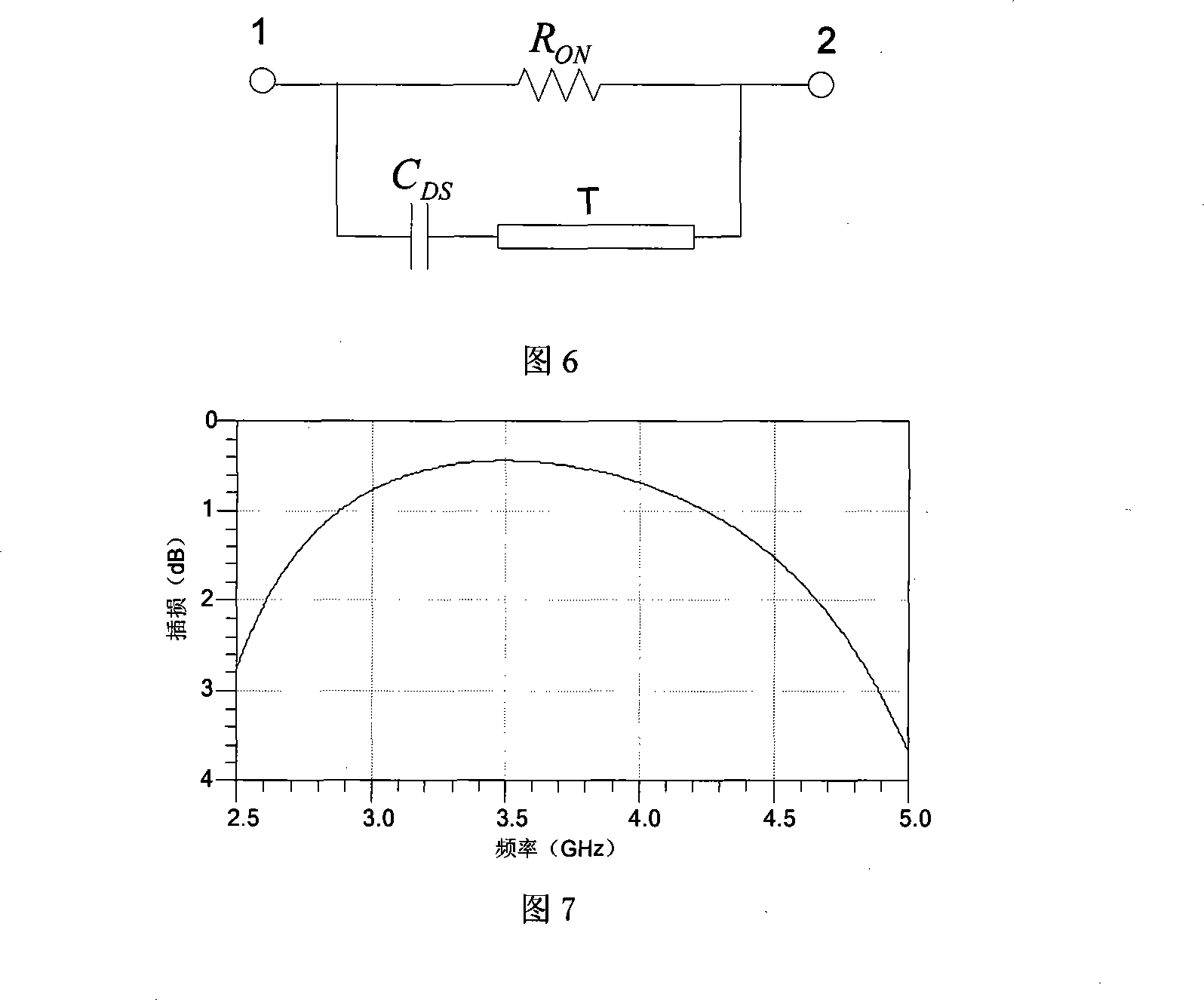
[0016] Figure 1 is the basic structure of an ordinary radio frequency switch circuit, where A and B are field effect transistors, and both ends of 1 and 2 are connected to the radio frequency channel. When the radio frequency switch is turned on, the state of the corresponding field effect tube is: tube A is on, and tube B is off; when the radio frequency switch is off, the state of the corresponding field effect tube is: tube A is off and tube B is on. Due to the non-ideality of the device, the switch tube is approximately equivalent to a small resistance when it is turned on, and is approximately equivalent to a small capacitor when it is turned off. The RF switch with this structure generally has an insertion loss of about 0.5-1dB when it is turned on, and an isolation of about 20dB when it is turned off. The traditional effective way to improve the isolation is parallel resonant inductor. As shown in Figure 2, an inductor L is connected in parallel next to the field effect...
PUM
 Abstract
Description
Claims
Application Information