Pleating device

A scraper and material feeding technology, which is applied in the field of pleating devices, can solve the problems of inconvenient pleating and uneven pleating, and achieve the effect of simple structure and convenient use

Inactive Publication Date: 2008-04-16
高国兴
View PDF0 Cites 4 Cited by
  • Summary
  • Abstract
  • Description
  • Claims
  • Application Information

AI Technical Summary

Problems solved by technology

[0003] The technical problem to be solved by the present invention is how to overcome the defect of uneven pleats produced by existing pleating devices, and provide a pleating device capable of producing uniform pleats
[0004] The technical problem to be solved by the present invention is how to overcome the inconvenient defect of existing pleating devices to make pleats of different widths, and provide a pleating device that can conveniently make pleats of different widths

Method used


Image

  • Pleating device
  • Pleating device
  • Pleating device

Examples


Embodiment approach 1

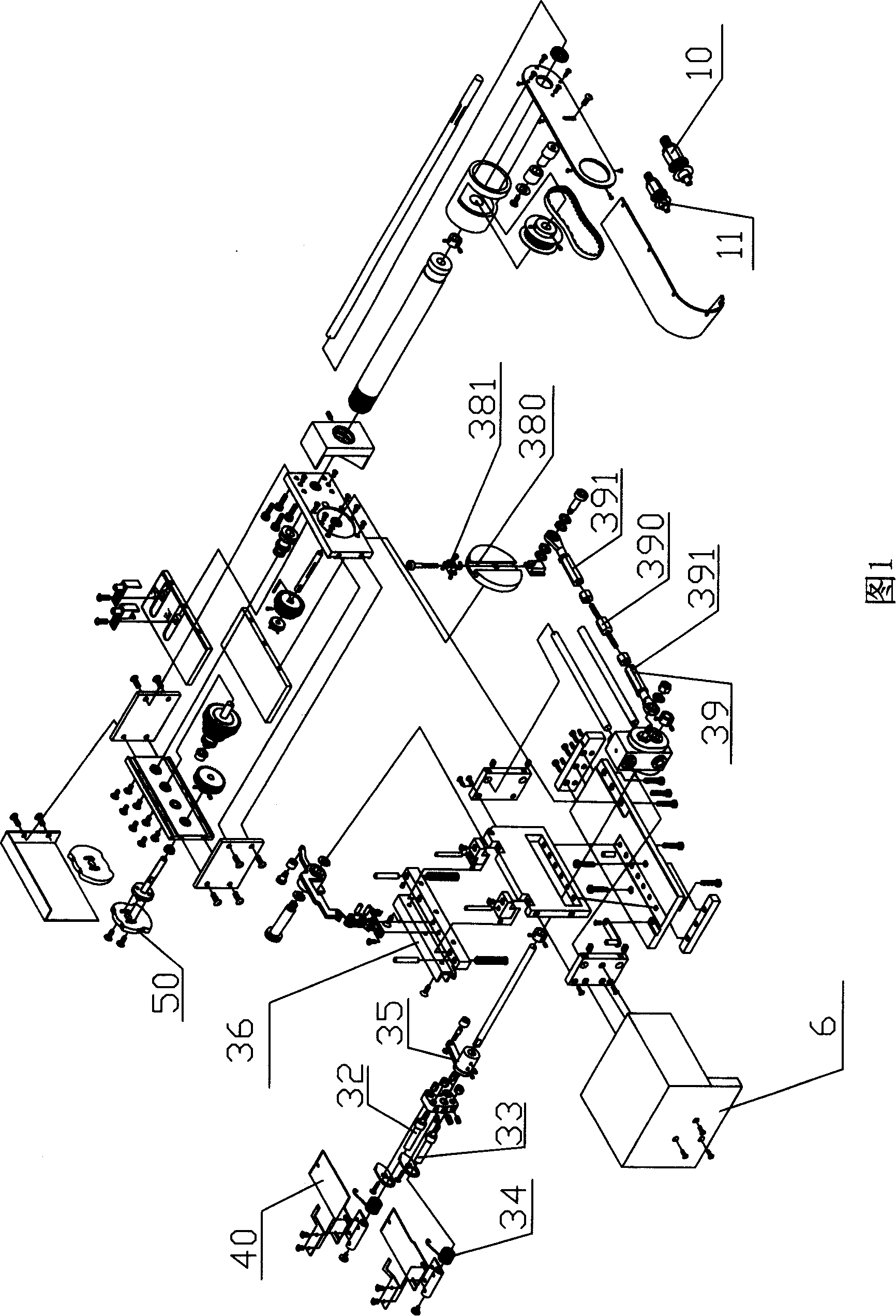
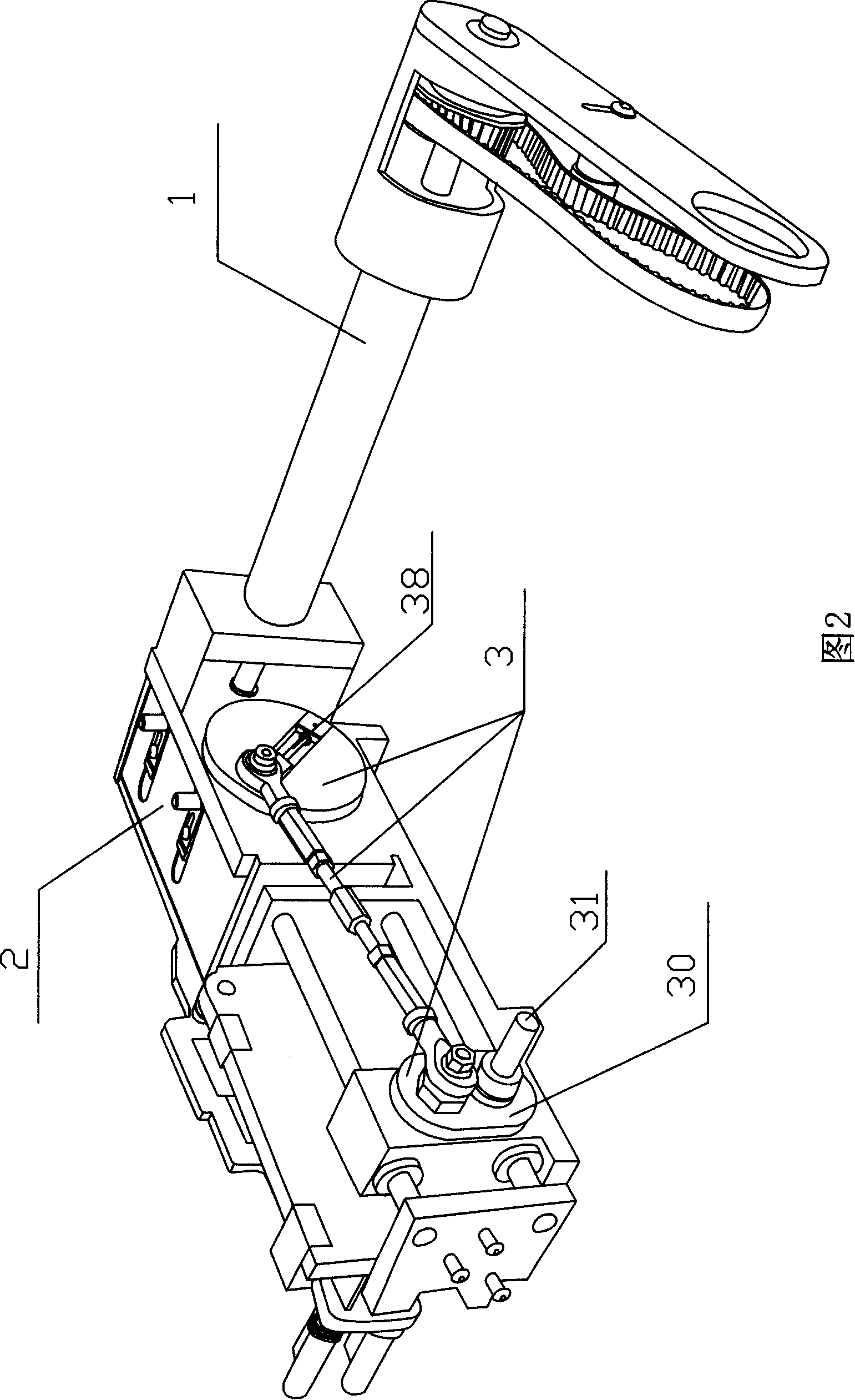
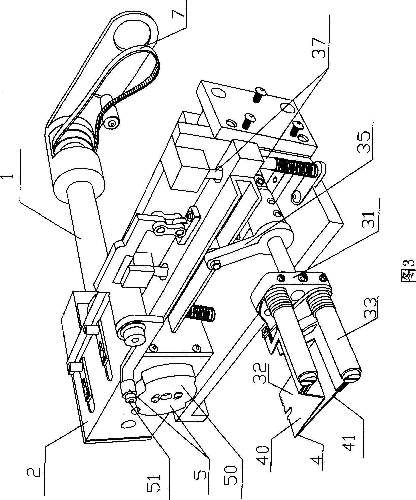
[0026] Embodiment 1: As shown in Figures 1, 2 and 3, the pleating device includes a transmission mechanism 1, a four-gear gearbox 2, a crank slider mechanism 3 and a feeding blade 4. The transmission mechanism 1 is mainly composed of a synchronous belt mechanism. The transmission mechanism 1 transfers the rotation provided by the flywheel of the sewing machine to the crank slider mechanism 3 after being shifted by the four-gear gearbox 2, and then converted into the reciprocating motion of the feeding blade 4 by the crank slider mechanism 3. .

[0027] The transmission mechanism 1 is equipped with a large synchronous pulley 10 and a small synchronous pulley 11 to cooperate with the flywheel of the sewing machine. Different pulleys can be used to realize the primary speed change.

[0028] The feeding blade 4 is composed of a main blade 40 and an auxiliary blade 41, which cooperate up and down to clamp the raw material to be processed. The slider 30 in the slider crank mechani...

Embodiment approach 2

[0033] Embodiment 2: As shown in FIG. 5 , the contour line of the cam 50 includes four segments of circular arcs, wherein a group of opposite circular arcs has the same radius and is between the radii of the other two circular arcs; The above-mentioned arc lines are coaxial with the cam 50, and two adjacent arc lines are connected by a smooth transition line, and the cam 50 is used for pleating. The cam 50 moves for one week, and the feeding shovel 4 completes two feeding round trips: when feeding for the first time, the chute 36 is at the top dead center; when feeding for the second time, the chute 36 is at the bottom dead center; the feeding shovel When the knife 4 returns, the chute 36 is at the stop point.

[0034] The pleating device also includes a presser foot with an upturned front end, and the front end of the presser foot is higher than the top dead center of the feeding blade 4 . Other components and structures are as described in Embodiment 1.

Embodiment approach 3

[0035] Embodiment 3: This pleating device is equipped with two types of cams 50 for accordion pleats and covering pleats, and the rest of the components and structures are as described in Embodiment 1, and the figure is omitted.


PUM


Abstract

The present invention relates to a pleating device, in particular to a pleating device which can be assembled on a common sewing machine. The technical problem to be solved by the present invention is how to overcome the defects that: pleats produced by the prior pleating device are uneven, and the widths of the pleats are inconvenient to be adjusted. Therefore, the present invention comprises a transmission mechanism, a crank-slider mechanism and a feeding shovel blade which are connected in sequence, wherein, the rotation provided by a power source is transmitted to the crank-slider mechanism by the transmission mechanism, and transformed into the reciprocating motion of the feeding shovel blade by the crank-slider mechanism. The present invention is characterized in that: the feeding shovel blade consists of a main shovel blade and a minor shovel blade which are mutually matched up and down for clamping the raw materials to be processed. After the proposal is adopted, the present invention has the advantages of simple structure and convenient use, and is suitable to produce the pleats in various widths, which is an ideal upgrading product for the prior pleating device.

Description

technical field [0001] The invention relates to a pleating device, in particular to a pleating device which can be assembled on a common sewing machine. Background technique [0002] When sewing fabrics, especially curtains or bedspreads, pleating is often required. The existing pleating device comprises a transmission mechanism, a slider crank mechanism and a feeding blade. The transmission mechanism transmits the rotation provided by the power source to the slider crank mechanism, which is then converted into the reciprocating motion of the feeding blade by the slider crank mechanism. The feeding shovel of the existing pleating device relies on friction to push the fabric to be fed. It is easy to slip when processing smooth or heavy fabrics, and the pleats produced are uneven; when the existing pleating device pleats with different widths, it needs to be replaced. Different cams, inconvenient. Contents of the invention [0003] The technical problem to be solved by th...

Claims


Application Information

Patent Timeline
Patent Type & Authority Applications(China)
IPC IPC(8): D05B35/08
Inventor 高国兴
Owner 高国兴
Why Eureka
Try Eureka