
Waving piston transducing device and method

A piston and piston cylinder technology, applied in the field of renewable energy applications, can solve the problems of low power generation, poor power generation quality, strong energy, etc., and achieve the effects of high energy conversion efficiency, simple structure, and convenient implementation

Inactive Publication Date: 2008-04-16
祁国英
View PDF0 Cites 2 Cited by
  • Summary
  • Abstract
  • Description
  • Claims
  • Application Information

AI Technical Summary

Problems solved by technology

[0002] Since the oil crisis in the 1970s, countries began to shift their attention to the use of local resources and the search for suitable and cheap energy. The 21st century is the century of the ocean. It has become an inevitable trend for human beings to obtain resources from the sea. After the fastest-growing use of marine energy, so far, countries and regions in the world such as Japan, the United Kingdom, Ireland, Norway, Spain, Sweden, Denmark, India, the United States and my country have established wave power generation devices on the sea. On the sea, or fixed on the coast, scientists from various countries have put forward more than 300 ideas and invented various power generation devices for more than 100 years. my country is in the leading position in the world in wave power generation technology. The two hundreds of kilowatt-level wave power generation devices that have been built are both national key research projects. So far, wave power generation technology has not yet reached the level of popularization and application.
[0003] Wave energy is the most unstable energy among renewable energy sources. Waves cannot be produced regularly, and have the characteristics of strong energy, slow speed and periodic changes. The shortcomings of existing technologies are: 1) low efficiency of energy harvesting; 2) converted Secondary energy is unstable; 3) Poor adaptability to sea environment

Method used


Image

  • Waving piston transducing device and method

Examples


Embodiment Construction

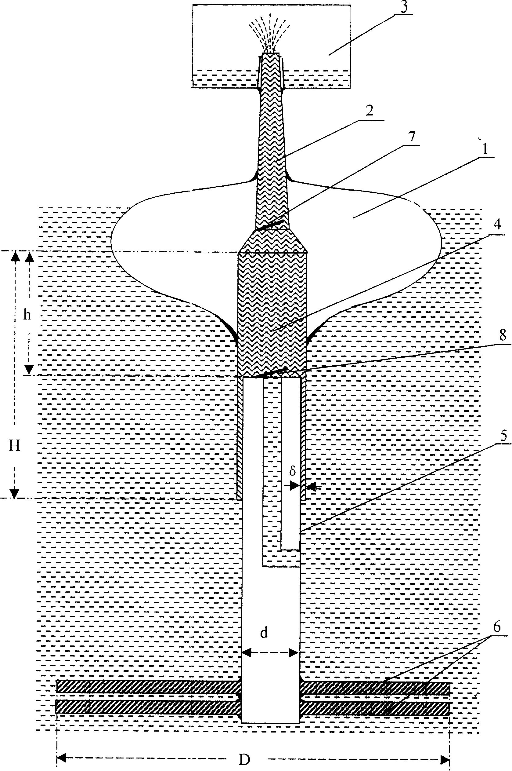
[0015] Such as figure 1 As shown, the wave piston energy conversion device of the present invention is an offshore structure, which consists of two parts: one part is a high-level reservoir 3 for receiving and energy conversion, and the other part is an energy harvesting device placed under the reservoir and floating on the sea surface. system unit.

[0016] The above-mentioned high-level reservoir built on the sea is integrated with the main structure, and its height is determined by the design water head height requirements. It provides a fixed-height head-stable energy source for the application of secondary energy. Under the action of wave energy, The purpose of energy conversion is achieved by pressurizing seawater and injecting it into the high-level reservoir.

[0017] The energy harvesting unit device below the reservoir includes a set of piston cylinders 4 placed in the sea and a contained piston body 5. Above the piston cylinders is a pressurized pipe 2 connected th...


PUM


Abstract

The invention relates to a fluctuant piston energy exchange device and comprises: a high level reservoir for receiving and energy exchange which is formed on the sea; a collecting energy system unit which is arranged under the reservoir and comprises a set of piston barrel arranged into the sea and embedded piston body, with a rim pipe arranged above the piston barrel and running through the piston barrel, a floating ball on the sea level covered on the piston barrel and the rim pipe, a non-return check valve arranged in the rim pipe, and a water intake forcing check valve arranged on the piston body; and more than one level of resistance baffleplates arranged at the lower end of the piston body. The floating ball and the piston barrel are two assemblies which are in nonrigid connection; the length of fit of the piston barrel arranged in the sea area and the embedded piston body is more than the maximum wave height in the sea area. The invention can transform the regenerative wave energy into effective mechanical energy, and can be directly applied to power generation, factories building at sea, seawater desalination and hydrogen production and manganese nodule exploration.

Description

technical field [0001] The invention belongs to the technical field of renewable energy applications, and in particular relates to a device and method for energy conversion of a wave piston. Background technique [0002] Since the oil crisis in the 1970s, countries began to shift their attention to the use of local resources and the search for suitable and cheap energy. The 21st century is the century of the ocean. It has become an inevitable trend for human beings to obtain resources from the sea. After the fastest-growing use of marine energy, so far, countries and regions in the world such as Japan, the United Kingdom, Ireland, Norway, Spain, Sweden, Denmark, India, the United States and my country have established wave power generation devices on the sea. On the sea, or fixed on the coast, scientists from various countries have put forward more than 300 ideas and invented various power generation devices for more than 100 years. my country is in the leading position in the...

Claims


Application Information

Patent Timeline
Patent Type & Authority Applications(China)
IPC IPC(8): F03B13/16
CPCY02E10/38Y02A20/144Y02E10/30
Inventor 祁国英
Owner 祁国英
Learn More