
Ion injector

An ion implanter and ion beam technology, which is applied in the manufacture of discharge tubes, electrical components, semiconductors/solid-state devices, etc., can solve the problems of increased power consumption, increased possibility, and large power consumption of the analysis electromagnet, achieving reduction in size and The effect of power consumption

Inactive Publication Date: 2008-04-16
NISSIN ION EQUIP CO LTD
View PDF2 Cites 10 Cited by
  • Summary
  • Abstract
  • Description
  • Claims
  • Application Information

AI Technical Summary

Problems solved by technology

Moreover, the possibility that the magnetic field (this magnetic field is also referred to as a fringe field) outside the yoke 36 generated by the connection parts 16, 22 interferes with the shape of the ion beam 2 (referring to shape and posture, the same below) increases.
[0022] (2) The power consumption of the coils 12 and 18 is relatively large
Therefore, the power consumption further increases
[0025] As described above, when the power consumption of the coils 12, 18 is large, the power consumption of the analysis electromagnet 40 is large, and thus the power consumption of the ion implanter is also large

Method used


Image

  • Ion injector
  • Ion injector
  • Ion injector

Examples


Embodiment Construction

[0145] (1) Regarding the entire ion implanter

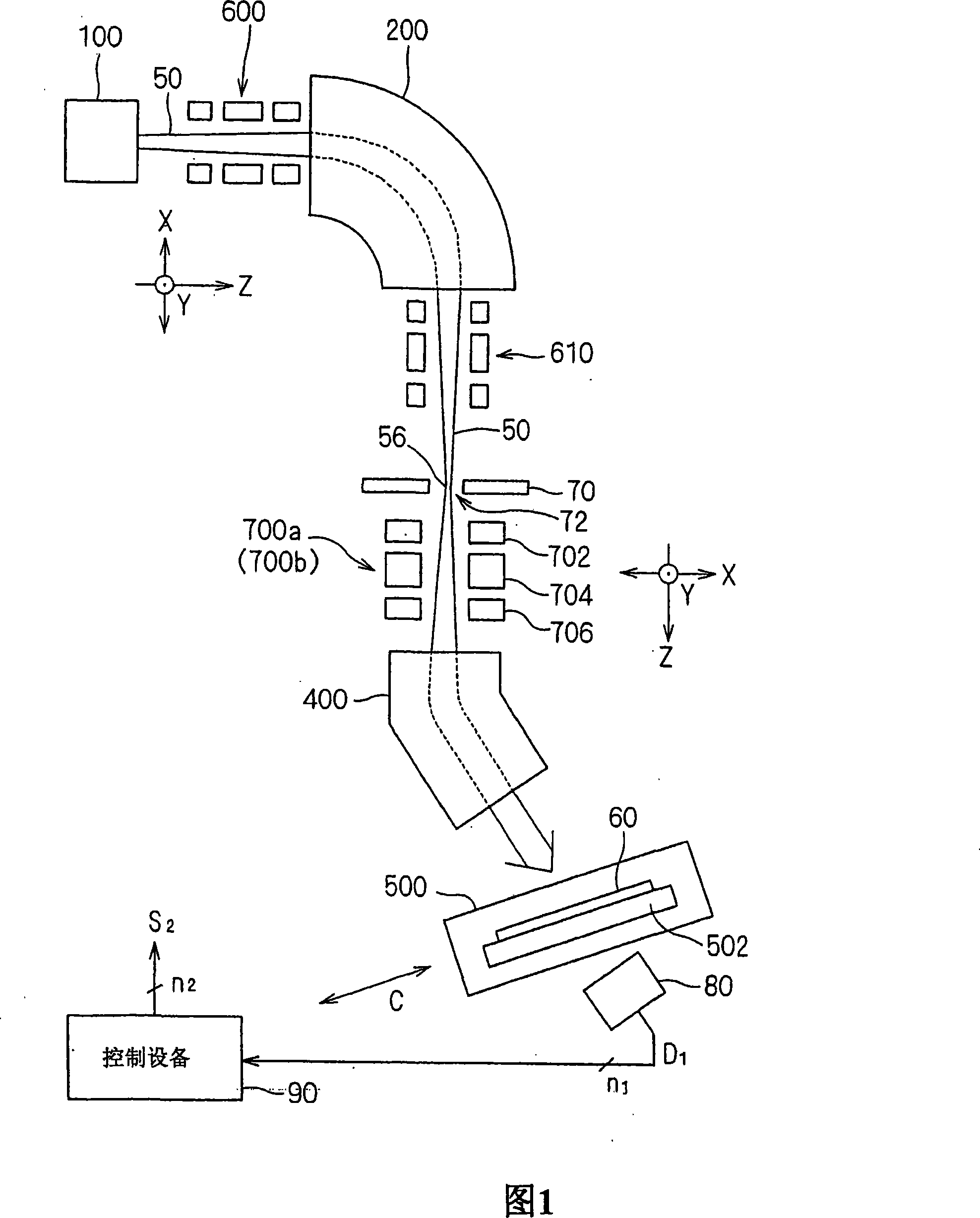
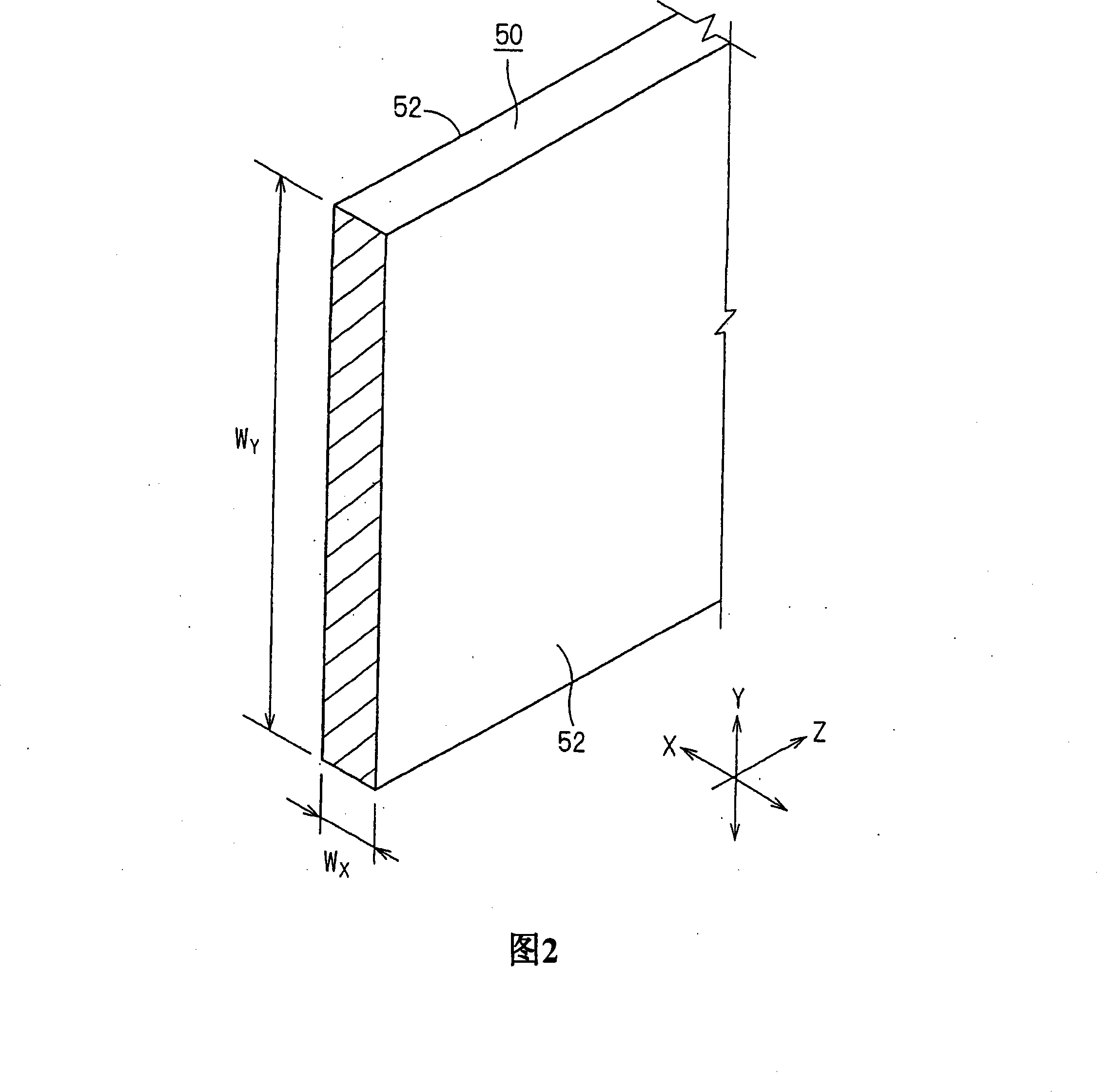
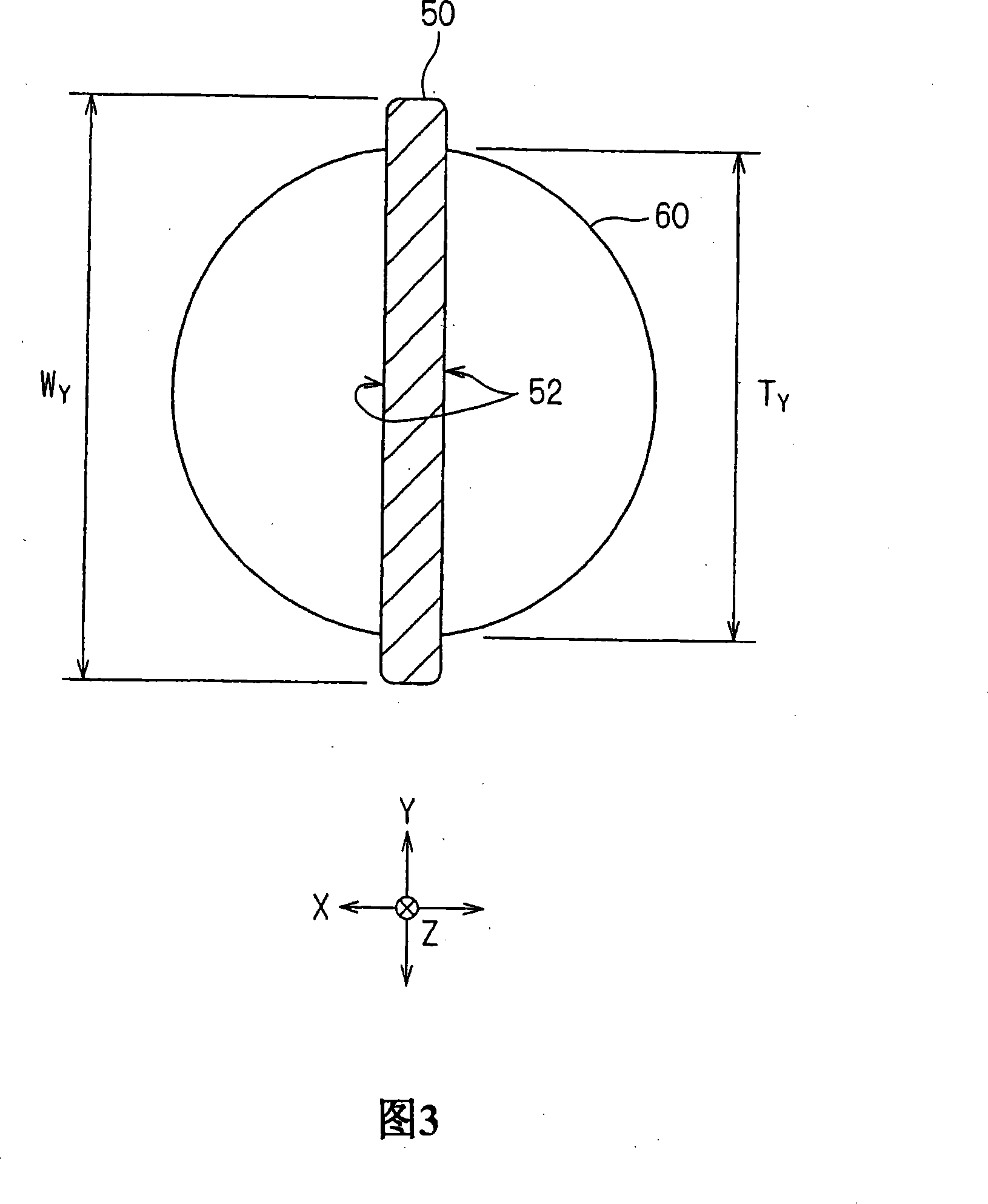
[0146] FIG. 1 is a schematic plan view showing an embodiment of an ion implanter of the present invention. In the specification and drawings, the transmission direction of the ion beam 50 is always set as the Z direction, and two directions substantially perpendicular to each other on a plane substantially perpendicular to the Z direction are set as the X and Y directions, respectively. For example, the X and Z directions are horizontal and the Y direction is vertical. The Y direction is a constant direction, while the X direction is not an absolute direction, but varies according to the position of the ion beam 50 on the path (eg, see FIGS. 1 and 4 , etc.). In the specification, the case where the ions constituting the ion beam 50 are positive ions is described as an example.

[0147] The ion implanter is an ion implanter for irradiating a ribbon ion beam 50 on a substrate 60 to perform ion implantation, and it includes: an io...


PUM


Abstract

An analyzing electromagnet which forms the ion implantation device comprises a first interior loop, a second interior loop, three first exterior loops, three second exterior loops and a yoke. The interior loop is saddle-shaped loop and collaborates with each other to generate the main magnetic field which bends the ion beam in the X-direction. Each exterior loop is saddle-shaped loop which generates a secondary magnetic field that revises the main magnetic field. Each loop has the structure that the groove part lies in the flabellate cylindrical band wound coil and the band wound coil is configured as follows: the periphery surface of the laminated-sheet insulator is winded with the laminated-sheet multi-turn of the insulation sheet and the conductor sheet; and the periphery surface is formed with a laminated-sheet insulator.

Description

technical field [0001] The present invention relates to an ion implanter in which a ribbon ion beam passes through an analysis electromagnet to perform momentum analysis (for example, mass analysis) of the ion beam, and is then incident on a substrate, thereby performing ion implantation on the substrate. Background technique [0002] In order to perform ion implantation on, for example, a large substrate, an ion beam having a ribbon (also called a sheet or stripe, the same below) shape is sometimes used. [0003] An example of an ion implanter is disclosed in, for example, Patent Document 1, in which a ribbon-shaped ion beam passes through an analysis electromagnet to perform momentum analysis (for example, mass analysis, the same below) of the ion beam, and is then incident on a substrate. , thereby performing ion implantation on the substrate. [0004] An example of an analysis electromagnet for momentum analysis of a ribbon ion beam is disclosed in, for example, Patent ...

Claims


Application Information

Patent Timeline
IPC IPC(8): H01J37/317H01L21/265
CPCH01J37/05H01J37/14H01J37/252H01J37/256H01J37/304H01J37/3171H01J37/3266H01J2237/141H01J2237/1415
Inventor 山下贵敏池尻忠司田中浩平赵维江田中秀之
Owner NISSIN ION EQUIP CO LTD
Learn More