Magnetic transmission fluent metal magnetofluid wave energy direct electricity generation unit device

A magnetic fluid power generation and liquid metal technology, applied in electromechanical devices, ocean energy power generation, electrical components, etc., can solve the problems of difficulty in generating induced electromotive force, destroying flow channel seals, reducing energy conversion efficiency, etc., and achieving easy commercialization. , High conversion efficiency, the effect of improving energy conversion efficiency

Inactive Publication Date: 2008-04-16
INST OF ELECTRICAL ENG CHINESE ACAD OF SCI +1
View PDF4 Cites 10 Cited by
  • Summary
  • Abstract
  • Description
  • Claims
  • Application Information

AI Technical Summary

Problems solved by technology

On the one hand, the elastic bellows has the characteristics of a spring, and it is easy to resonate, so that the liquid metal oscillates back and forth at a certain point, and it is difficult to generate an induced electromotive force
On the other hand, the bellows is in the reciprocating motion of expansion and contraction for a long time, and it is easy to break, destroy the seal of the flow channel, leak liquid metal, and pollute the marine environment; at the same time, it brings a series of problems such as maintenance and reliability.
In addition, the liquid metal is in direct contact with the bellows, which increases the flow resistance and reduces the energy conversion efficiency

Method used


Image

  • Magnetic transmission fluent metal magnetofluid wave energy direct electricity generation unit device
  • Magnetic transmission fluent metal magnetofluid wave energy direct electricity generation unit device

Examples


Embodiment Construction

[0016] The present invention will be further described below in conjunction with the accompanying drawings and specific embodiments.

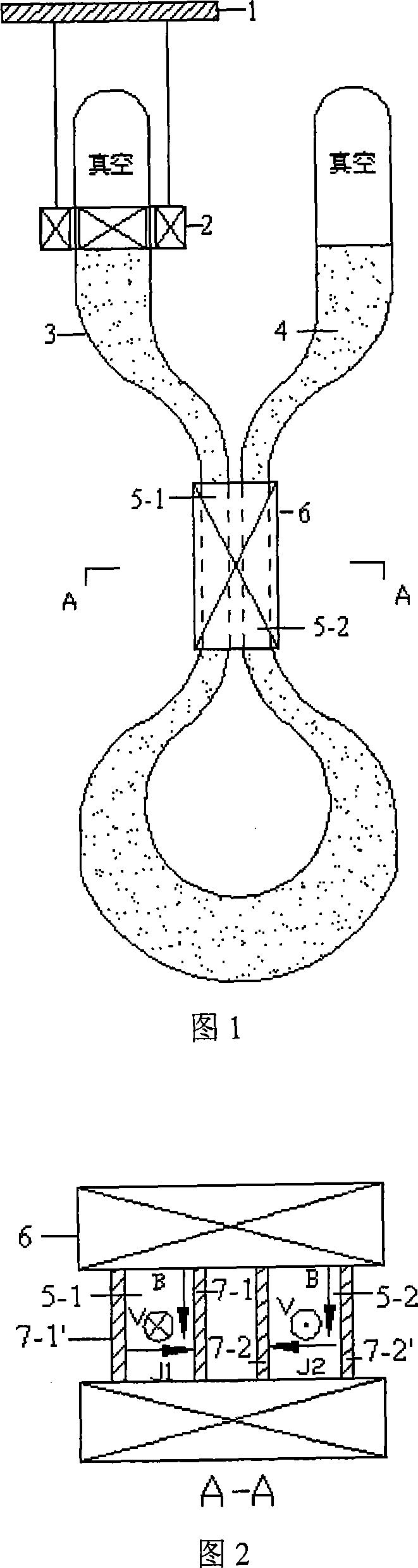
[0017] Fig. 1 is a schematic structural diagram of a specific embodiment of the present invention. As shown in Figure 1, the specific embodiment of the present invention consists of a pressure plate 1, a magnetic coupling piston 2, a U-shaped sealed pipeline 3 equipped with liquid metal 4, a left channel 5-1 for magnetic fluid power generation, and a right channel 5-2 for magnetic fluid power generation Composed of two pole magnets 6, vertically arranged in seawater near the sea surface.

[0018] The U-shaped sealed pipeline 3 is a sealed pipeline space made of non-magnetic and non-conductive materials, and the two ends are vacuum; it consists of left and right straight line sections, left and right tapered sections, magnetic fluid power generation left channel 5-1 and The right passage 5-2 and the annular section are composed, and the liquid ...


PUM


Abstract

The invention discloses a generating unit adopting magnetic-transmission fluid metal (the magnetic fluid wave energy is used to generate electricity directly), comprising a pressure plate (1), a magnetic-coupling piston (2), a U-shape gland (3), fluid metal (4), a left magnetic-fluid generating channel (5-1) with a rectangular or quadratic cross-section, a right magnetic-fluid generating channel (5-2), two pairs of flat electrodes (7-1), (7-1') and (7-2), (7-2') and two polar magnets (6), and the invention is vertically arranged in the offshore seawater. The pressure plate (1) linked with a buoy drives the magnetic-coupling piston (2) to make reciprocating movements; the liquid metal (4) in the U-shape gland (3) is driven to flow under the magnetic coupling function. As a result, zero leakage of liquid metal (4) is realized, the flow resistance of the liquid metal (4) is reduced, the efficiency of energy conversion and the stability of the generating system are improved.

Description

technical field [0001] The invention relates to a liquid metal magnetic fluid wave energy direct power generation device, in particular to a liquid metal magnetic fluid wave energy direct power generation unit which adopts a non-contact magnetic coupling piston to transmit ocean wave energy. technical background [0002] Ocean wave energy is a clean and renewable energy source with low-speed, high-force motion characteristics. Compared with renewable energy such as wind energy and solar energy, the development and utilization of wave energy still has great difficulties and challenges in engineering. So far, a variety of methods of utilizing wave energy to generate electricity have been developed, such as the oscillating water column type using a high-speed rotating generator, the embankment type, the Archimedes wave pendulum using a permanent magnet linear generator, and using magnetic fluid (MHD) to generate electricity. Machine magnetic fluid wave energy generator. [00...

Claims


Application Information

Patent Timeline
Patent Type & Authority Applications(China)
IPC IPC(8): H02K44/08F03B13/14
CPCY02E10/38Y02E10/30
Inventor 彭燕赵凌志沙次文李然许玉玉林佐伟刘保林李建贾龙
Owner INST OF ELECTRICAL ENG CHINESE ACAD OF SCI
Why Eureka
Try Eureka