Pressure regulating on-off circuit

A voltage regulating switch, circuit technology, applied in electrical components, output power conversion devices, conversion equipment that can be converted to DC without intermediate conversion, etc., can solve the problem of extra power consumption, limited voltage regulation range, large potentiometer, etc. problem, to achieve the effect of simple circuit structure, low power consumption, and low heat generation of the instrument

Inactive Publication Date: 2008-04-16
冯筠荪 +1
View PDF3 Cites 12 Cited by
  • Summary
  • Abstract
  • Description
  • Claims
  • Application Information

AI Technical Summary

Problems solved by technology

However, due to the voltage regulation of this circuit through the relay control suction and release switching method, the voltage regulation range is limited, and it is still difficult to achieve continuous stepless voltage regulation
[0005] Due to the dynamic and static characteristics of the electromagnet, the instrument for testing the performance of the electromagnet has special requirements on the power supply. According to the above-mentioned prior art AC power rectification and voltage regulation circuit principle and related patented technical improvement schemes, in the static performance test , in order to obtain a test voltage that can be continuously changed, a potentiometer is usually used to adjust the voltage on the DC output circuit, but the use of the potentiometer often forms a large internal resistance, which requires additional power consumption and affects the test accuracy; while in dynamic performance In the test, it is often impossible to obtain a stable and high switching frequency by means of relay contacts or manual on-off of the board key, which affects the test effect of dynamic performance
Therefore, these have brought certain difficulties to the electromagnet performance detection technology, and further research and improvement are still awaited.

Method used


Image

  • Pressure regulating on-off circuit
  • Pressure regulating on-off circuit
  • Pressure regulating on-off circuit

Examples


Embodiment Construction

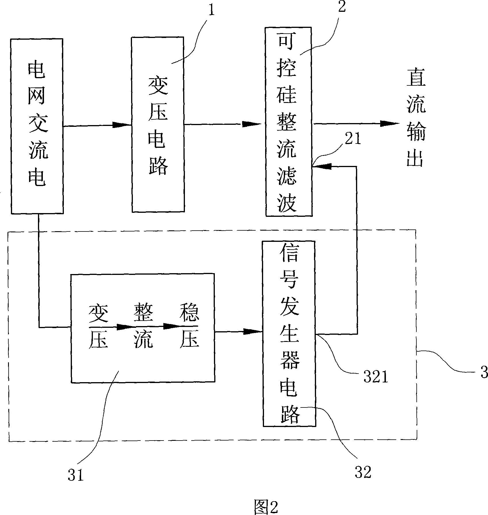
[0022] The present invention will be further described in detail below in conjunction with the accompanying drawings and embodiments.

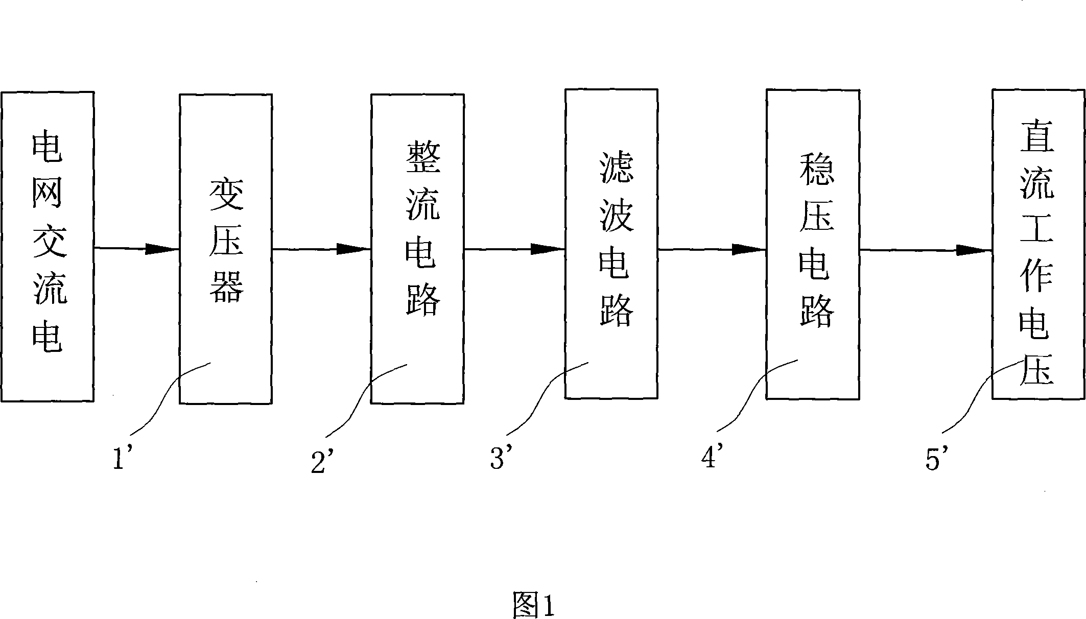
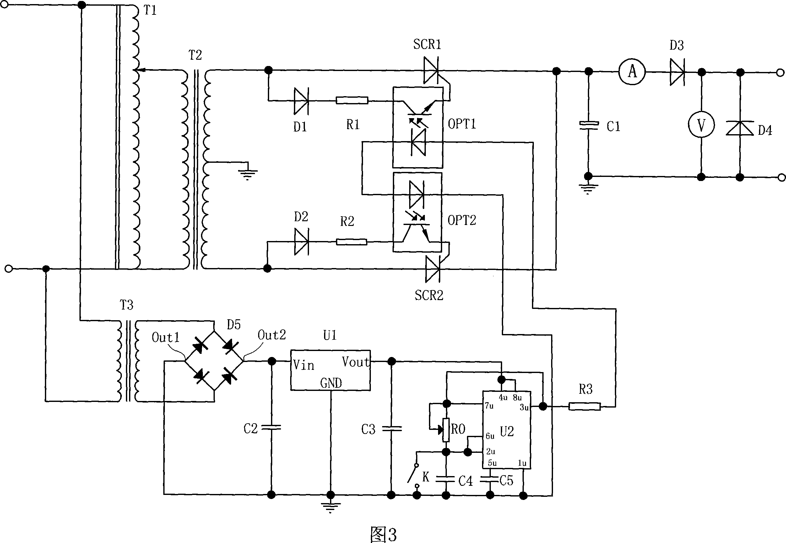
[0023] As shown in Fig. 2, it is a schematic block diagram of the circuit of the present invention, the voltage regulating switch circuit includes a transformer circuit 1 that realizes the high and low voltage transformation of the input AC power supply, and realizes the rectification of the secondary AC power after the above-mentioned voltage transformation , a silicon controlled rectifier filter circuit 2 for filtering, and a trigger circuit 3 for controlling the on and off of the silicon controlled rectifier filter circuit. Wherein, the voltage transformation circuit 1 includes a main circuit transformer T2, and also includes an AC voltage regulator T1 connected to the main circuit transformer T2, and the input terminals of the silicon controlled rectifier circuit 2 are respectively connected to the voltage transformation circuit 1 and the ...


PUM


Abstract

The invention discloses a voltage-regulation switching circuit, comprising a voltage circuit (for conversion of high/low voltage of the imported AC power supply), a controllable silicon rectifying filter circuit (connected to the output end of the voltage-transforming circuit, and rectifying and filtering the secondary alternating current) and a trigger circuit (used to control the rectifying filter circuit to switch on/off). The voltage-transforming circuit comprises a main circuit transformer and also comprises an AC booster connected to the main circuit transformer; the trigger circuit comprises an auxiliary DC power-supply circuit and a signal generator circuit; the trigger and conduction end of the controllable silicon rectifying filter circuit is connected to the signal output end of the signal generator circuit. The invention adopts an AC booster to regulate the output voltage; because no potentiometer is adopted, no extra power loss occurs, and as a result, the normal operation of the electromagnet testing circuit under high power is achieved; besides, controllable silicon rectifying filter circuit can be adopted to realize switching control of 0 up to 30 times/second.

Description

technical field [0001] The invention belongs to the technical field of rectification and voltage regulation circuits for AC power supplies, in particular to a power supply voltage regulation switch circuit for instruments or equipment used to detect dynamic and static characteristics of electrical components such as electromagnets or relays. Background technique [0002] Electromagnet is an electromagnetic actuator commonly used in mechatronics and automatic electrical control systems. As a power element, its performance directly affects the overall performance of the components and devices it constitutes. Therefore, it is important to test the performance of electromagnets. very necessary. Regarding the performance index of the electromagnet, there are usually two types of static performance and dynamic performance. The testing process requires the electromagnet testing instrument to provide working current and voltage that meet certain requirements. When performing static...

Claims


Application Information

Patent Timeline
Patent Type & Authority Applications(China)
IPC IPC(8): H02M7/155H02M5/12
Inventor 冯筠荪陆烨
Owner 冯筠荪
Why Eureka
Try Eureka