Solid-state imaging pickup device, camera, automobile and monitoring device
A technology for a solid-state imaging device and a video camera is applied in the fields of solid-state imaging devices, automobiles, monitoring devices, and cameras, and can solve problems such as difficult quality requirements and increased cost.
- Summary
- Abstract
- Description
- Claims
- Application Information
AI Technical Summary
Problems solved by technology
Method used
Image

Examples
Embodiment 1
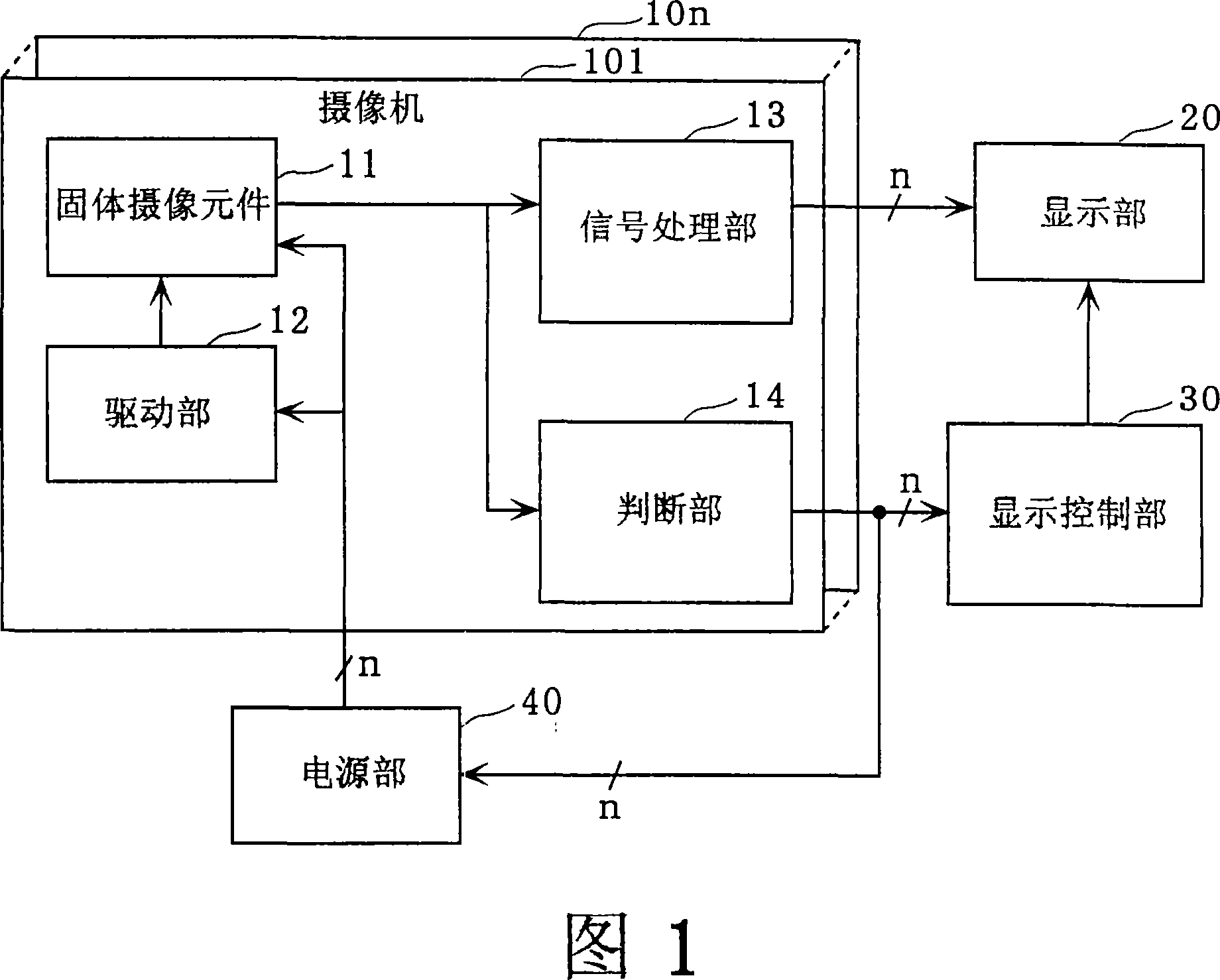
[0157] FIG. 1 is a block diagram showing the configuration of a camera system in the first embodiment. The camera system in this figure includes n cameras 101 to 10n, a display unit 20 , a display control unit 30 , and a power supply unit 40 . Each camera includes a solid-state imaging element 11 , a drive unit 12 , a signal processing unit 13 , and a determination unit 14 .
[0158] The solid-state imaging element 11 outputs signals of a plurality of pixels according to various driving signals supplied from the driving unit 12 . The signals of the plurality of pixels contain a reference signal with a fixed level, and the reference signal with a fixed level is used for detecting malfunction, that is, for judging a fault. The drive unit 12 drives the solid-state imaging element 11 by outputting various drive signals. The signal processing unit 13 generates an image based on signals of a plurality of pixels output from the solid-state imaging element 11 . The judging unit 14 ...
Embodiment 2
[0180] The configuration of the camera system in this embodiment is almost the same as that in FIG. 1 , except that a solid-state imaging device 21 shown in FIG. 13 is provided instead of the solid-state imaging device 11 . Hereinafter, differences will be described in detail, and descriptions of similarities will be omitted.
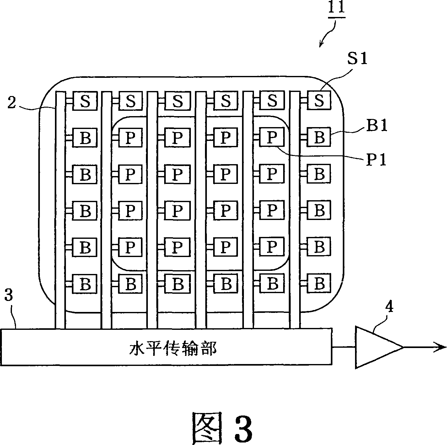
[0181] FIG. 13 is a block diagram showing the configuration of the solid-state imaging device 21 in the second embodiment. The solid-state imaging device 11 in this figure differs from the solid-state imaging device 11 shown in FIG. 3 in that a reference signal generating unit 5 is newly added and all pixel units S1 are replaced by pixel units B1.
[0182] The reference signal generating unit 5 injects reference charges corresponding to the reference signal into the uppermost upstream of each vertical transfer unit 2 . Accordingly, the charge injection portion of the pixel portion S1 becomes unnecessary. The reference signal generator 5 has an IS elec...
Embodiment 3
[0187] The configuration of the camera system in this embodiment is almost the same as that in FIG. 1 , except that a solid-state imaging device 31 shown in FIG. 14 is provided instead of the solid-state imaging device 11 . Hereinafter, the description will focus on the points of difference, and the description of the points of similarity will be omitted.
[0188] FIG. 14 is a block diagram showing the configuration of the solid-state imaging device 31 in the third embodiment. The solid-state imaging device 31 in this figure includes: a plurality of photoelectric conversion sections arranged in a matrix, a vertical scanning section 6, a horizontal scanning section 7, and an output amplifier 8, and the vertical scanning section 6 sequentially selects the rows of the photoelectric conversion sections. , the horizontal scanning section 7 sequentially selects the columns of the photoelectric conversion section, the output amplifier 8 outputs signals through the output lines of eac...
PUM
 Abstract
Description
Claims
Application Information