Blast furnace bellless furnace top distributor

A technology of distributing device and bellless, applied in blast furnace, blast furnace details, blast furnace parts and other directions, can solve the problems of shortening the service life of working parts, no water cooling, shortening service life, etc., to save manufacturing cost and reduce working temperature , the effect of improving the service life

Active Publication Date: 2008-05-07
CISDI ENG CO LTD
View PDF3 Cites 18 Cited by
  • Summary
  • Abstract
  • Description
  • Claims
  • Application Information

AI Technical Summary

Problems solved by technology

The problems of these two devices are: one is that the lead screw is always exposed in the box, and it is easily polluted by the dust brought into the box by the gas, and it cannot be effectively protected, making it susceptible to wear and reducing the service life ; The second is that there is no water cooling for the blanking throat in the center, and the gap between its outer wall and the inner wall of the discharge chute support or the trunnion is too large, so that one end of the tilting shaft of the chute is exposed to the furnace, and the result is: this That is, it cannot reduce the temperature of the throat and improve the wear life of the throat, nor can it effectively protect the tilting axis of the chute; the third is that the torque driving the α angle of the chute is an upward pulling force. When the weight is heavy, the slewing bearing used for the rotation of the chute will lose stability and shake; the fourth is that the tilting axis of the chute passes through the center of the horizontal section of the throat pipe, so that the tilting arm of the device announced in CN98217856.5 is short, and the tilting arm bracket and trunnion The large stress and fast wear between the rotary sleeves eventually lead to accelerated deterioration of the controllable precision of the α angle; and the device disclosed in CN99815290.0, in order to increase the arm of force, increases the radius of rotation of the hinged parts of the tilting chute, causing the chute The gear diameter of the slewing support and the transmission lead screw in the lifting slewing frame increases, which increases the weight of the device and increases the manufacturing cost; in addition, the device disclosed by CN99815290.0 sets the chute rotation and slewing mechanism on the box shell In the lower part, the diameter of the gear used for the rotation transmission of the chute increases greatly, which not only increases the weight of the equipment, but also makes the gear used for the α-angle transmission of the chute and the gear used for the rotation transmission of the chute not on the same plane and fixed point, and its concentricity Reduced to ensure the concentricity of the two gears requires high manufacturing and processing requirements and difficult assembly
[0003] In the similar device announced by CN200510006349.7 patent, a water cooling pipeline is arranged on the outside of the feeding throat, and a design in which the tilting connecting rod of the chute is directly hinged with the suspension arm of the chute is adopted, but its defects are: first, the The cooling water pipeline is set around the outside of the heat dissipation wall of the throat, and the water pipe is not cast into the inside of the throat, which has poor heat transfer effect and cannot effectively reduce the temperature of the throat; secondly, the connecting rod used for the tilting of the chute It is directly hinged with the suspension arm of the chute, causing the suspension arm of the chute to extend into the inner space of the box body. Since the space is required to be isolated from the environment in the furnace, the clearance necessary for the rotation of the suspension arm of the chute increases the communication between the inner space of the box body and the environment in the furnace. area, it will increase the possibility of gas escaping into the box, and because most of the suspension arm is suspended in the high temperature environment in the furnace, its temperature is very high, which will cause the connecting rod and the chute suspension arm to work under high temperature conditions for a long time. It will inevitably reduce the service life of the working parts equipped at this point, and become the weak link in the patented device

Method used


Image

  • Blast furnace bellless furnace top distributor
  • Blast furnace bellless furnace top distributor
  • Blast furnace bellless furnace top distributor

Examples


Embodiment Construction

[0027] The present invention is described in detail below in conjunction with accompanying drawing:

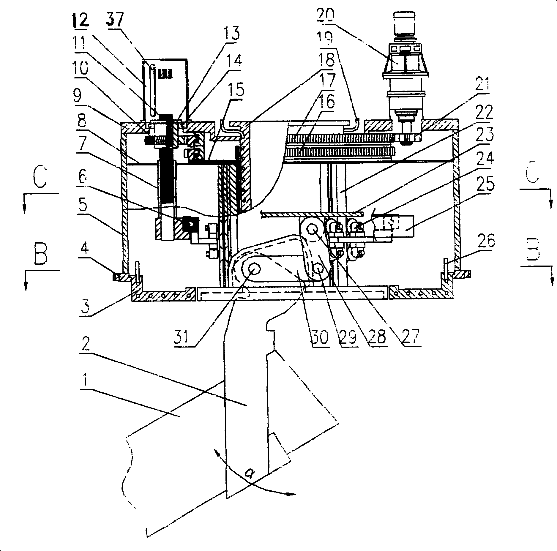
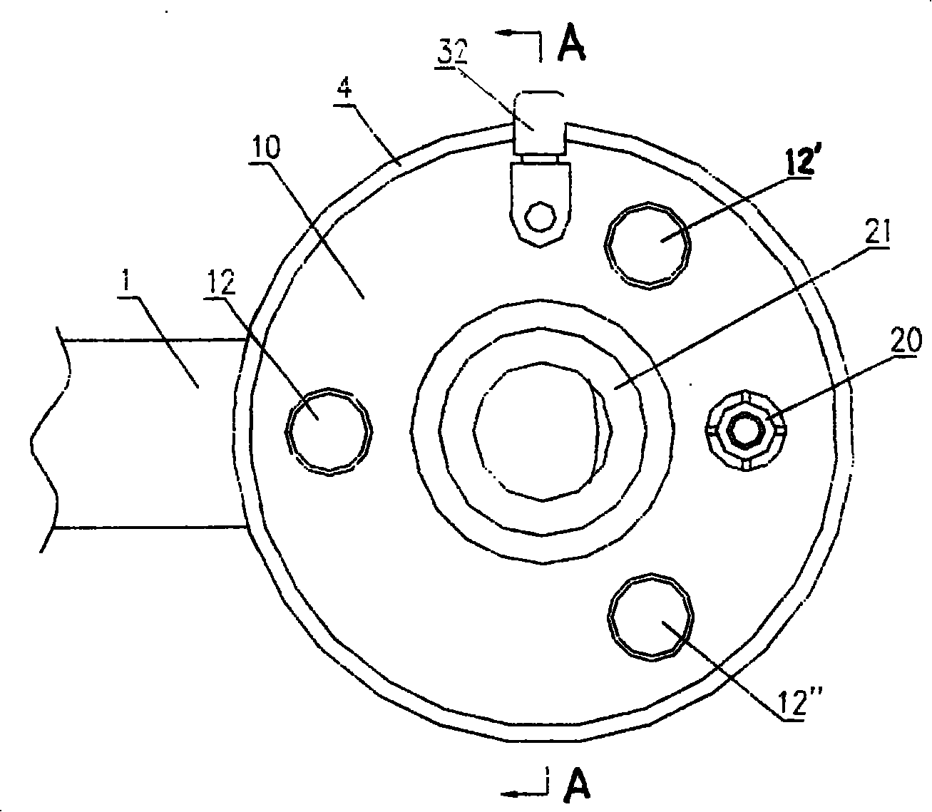
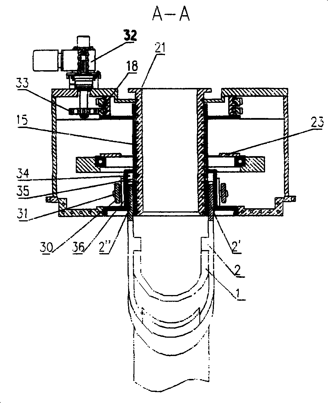
[0028] Such as figure 2As shown, above the device box cover 9, the water-cooled throat pipe 18 is vertically hoisted in the center, and two motors 20, 32 and three sealing covers 12, 12', 12 "are installed around the outer seat of the water-cooled throat pipe 18 ". Among them: a The motor 32 is used for the rotary drive of the chute, that is, the rotary motor; the other motor 20 is used for the tilting drive of the chute α angle, that is, the tilting motor. The three sealing covers 12, 12', 12" are distributed at 120° with the water-cooled throat 18 on the circumference of the common center. Such as figure 1 As shown, in the three sealing covers 12, 12', 12", there is a small slewing bearing 14 respectively installed concentrically with it, their outer rings are fixed with the box cover 9, and their inner rings are respectively connected with a ball screw pair The upper en...


PUM


Abstract

The invention discloses a bell-less top distributing gear of furnace, belonging to technical field of metallurgical industry. The invention adopts sealed cooling, a water-cooling venturi tube with pipe laying and a water-cooling chassis. A motor drives a chute to rotate and tilt; wherein, the motor drives the nut of the ball screw assembly to rotate and then drives the lead screw and the lifting rotary frame connected with the lead screw to move up and down in order to achieve chute to tilt for Alpha angle. The invention has the advantages of high coaxiality, high transmitting precision, long service life of the critical component, easy manufacture, light weight and low cost. The tilting Alpha angle of the chute and the stationarity of the tilting movement of the chute can be checked during the producing process of the furnace by the invention. The invention can be used in charging operation of furnace roof and also is suitable for shaft furnace or smelting reduction furnace which need to feed from the roof to the closed space and distribute regularly.

Description

technical field [0001] The invention belongs to the technical field of the metallurgical industry, and discloses a blast furnace bellless top charging device, which is a kind of mechanical equipment used for blast furnace top charging operations, and it is also suitable for charging from the top to a closed space, and Shaft furnace or smelting reduction furnace for regular cloth distribution. Background technique [0002] In Chinese patents CN98217856.5, CN99815290.0 and CN200510006349.7, three kinds of devices directly related to the present invention are disclosed. Among them, the devices disclosed by CN98217856.5 and CN99815290.0 patents, the tilting mode of the chute α angle is that the motor drives the gears to make the three lead screws rotate, and the rotation of the lead screws drives the nut and the chute lifting and turning frame fixed together with the nut. Moving up and down, the chute is driven by the tilting arm to tilt at an angle of α. The problems of these...

Claims


Application Information

Patent Timeline
Patent Type & Authority Applications(China)
IPC IPC(8): C21B7/00C21B7/20
Inventor 张昭贵陈映明邹忠平王蜀生彭学元熊拾根凌树渊朱宁赵渭康黄其明
Owner CISDI ENG CO LTD
Why Eureka
Try Eureka