Electrostatic discharge protecting equipment of connection pad and its method and structure
An electrostatic discharge protection and coupling technology, applied in the field of electrostatic discharge protection devices, can solve the problems of increasing circuit area and cost
- Summary
- Abstract
- Description
- Claims
- Application Information
AI Technical Summary
Problems solved by technology
Method used
Image
Examples
Embodiment Construction
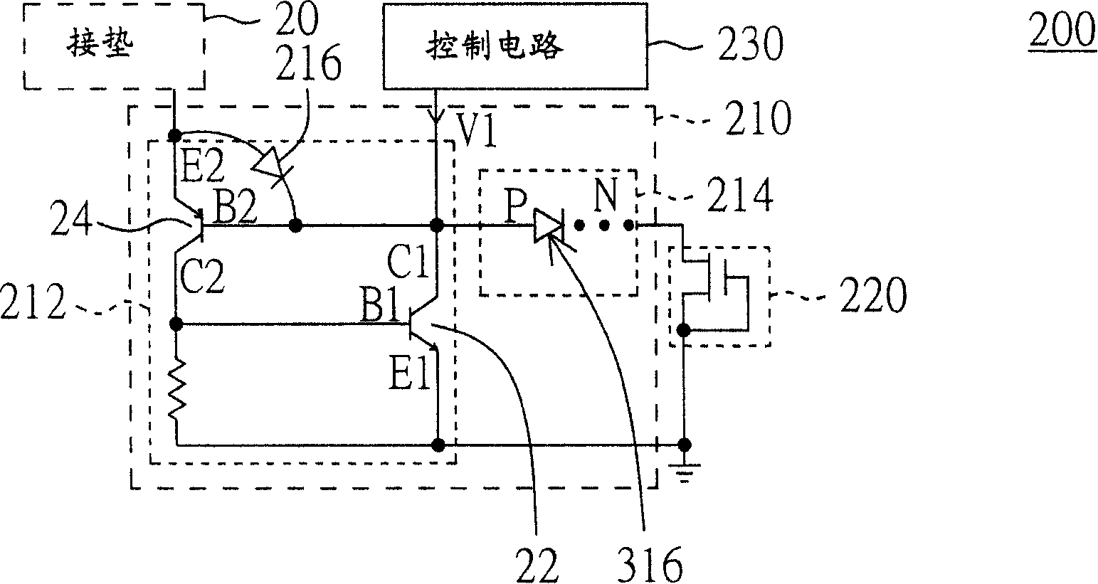
[0023] Please refer to Figure 2A , which is a circuit diagram of an electrostatic discharge protection device according to a preferred embodiment of the present invention. The ESD protection device 200 includes a regulation circuit 210 , a snapback component 220 and a control circuit 230 . The regulation circuit 210 includes a silicon controlled rectifier 212 . A silicon controlled rectifier 212 is coupled to the pad 20 , and the silicon controlled rectifier 212 includes a first diode 216 . The snapback component 220 can optionally be used with the diode circuit 214 . In the case of using the diode circuit 214, it is coupled to the N pole of the diode circuit 214 (such as Figure 2A As shown), in the case of not using the diode circuit 214, it is coupled to the N pole of the first diode 216 (not shown). The control circuit 230 is coupled to the N pole of the first diode 216 . In the normal operation mode, the control circuit 230 is used to provide a first voltage V1 (for...
PUM
 Abstract
Description
Claims
Application Information
 - R&D
- Intellectual Property
- Life Sciences
- Materials
- Tech Scout
- Unparalleled Data Quality
- Higher Quality Content
- 60% Fewer Hallucinations
Browse by: Latest US Patents, China's latest patents, Technical Efficacy Thesaurus, Application Domain, Technology Topic, Popular Technical Reports.
© 2025 PatSnap. All rights reserved.Legal|Privacy policy|Modern Slavery Act Transparency Statement|Sitemap|About US| Contact US: help@patsnap.com


