Eureka AIR delivers breakthrough ideas for toughest innovation challenges, trusted by R&D personnel around the world.

Antenna for a radar level gauge

A material level gauge and antenna technology, which is applied in the antenna field of radar level gauge, can solve problems such as troublesome, non-horizontal flange of the antenna, high cost, etc., and achieve the effect of simple maintenance

Inactive Publication Date: 2008-05-07
ROSEMOUNT TANK RADAR
View PDF3 Cites 15 Cited by
  • Summary
  • Abstract
  • Description
  • Claims
  • Application Information

AI Technical Summary

Problems solved by technology

Needless to say, this cleaning process is cumbersome and costly
Also, often parabolic antennae in tank installations create hidden spaces, such as above the parabola, where tank contents can accumulate
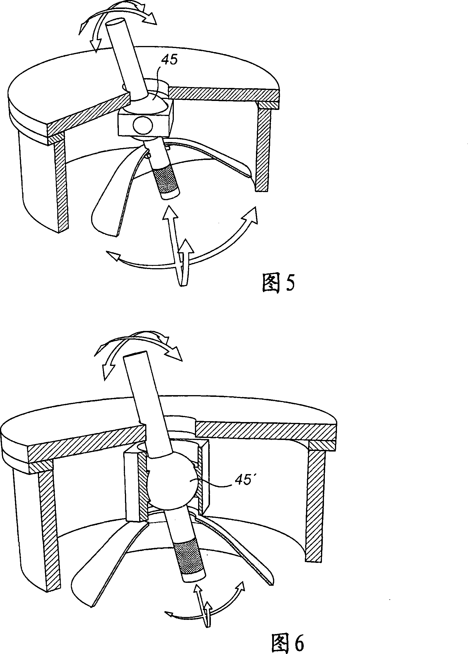
[0008] Another potential requirement for the antenna of a radar level measurement system is to adjust the direction of the radar beam to meet the needs of the vertical radar beam directed at the filling material, which may be difficult in practice depending on the specific container design
For example, the flange on which the antenna is mounted may be non-horizontal

Method used


Image

  • Antenna for a radar level gauge
  • Antenna for a radar level gauge
  • Antenna for a radar level gauge

Examples


Embodiment Construction

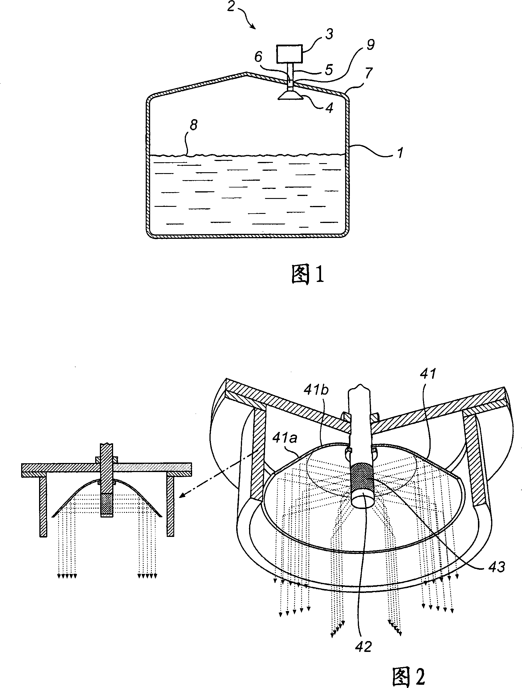
[0043] Fig. 1 schematically shows a radar level gauge system 2 comprising an antenna according to the invention. Briefly, the system in Fig. 1 comprises: an electronic unit 3 for transmitting and receiving radar signals and processing the received radar signals to determine the level 8 of the filling material in the tank 1; an antenna 4 arranged in the tank 1 inside, for transmitting radar waves and receiving radar waves entering the tank, which will be described in more detail below; Preferably, the same antenna may be used as a transmitter for emitting output radiation and as a receiver for receiving reflected back-reflected signals, although separate antennas may also be used for these functions. The radar level gauge is preferably arranged on the tank top 7 , whereby the waveguide 5 is arranged to protrude into the tank through the tank opening 6 .

[0044] In use, the radar level gauge 2 transmits radar energy along the waveguide 5 through the top of the tank and receive...


PUM


Abstract

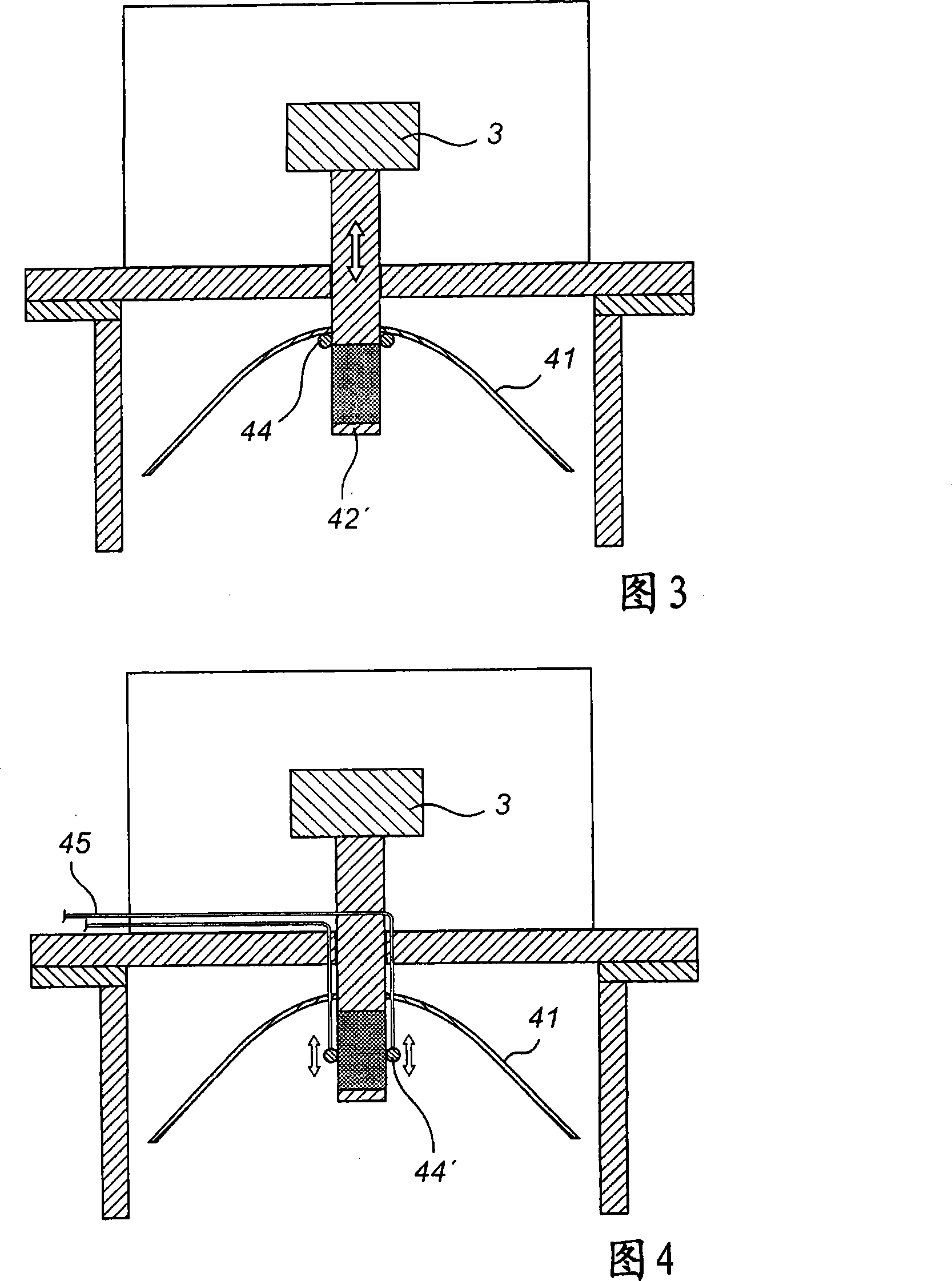
The present invention discloses an antenna for a radar-based level gauge, which is used for determining a filling level of a filling material contained in a container is disclosed. The antenna comprises a reflector, which is symmetric around a symmetry axis; and a feeder for feeding microwave signals to and from the reflector. The feeder is of an elongate, essentially cylindrical shape, with a longitudinal axis of said feeder essentially coinciding with said symmetry axis of the reflector, wherein said feeder comprises a ring-shaped radiation feeding area for transmitting electromagnetic radiation towards the reflector and for receiving reflected electromagnetic radiation. In a preferred embodiment, an abutment ring is arranged around the feeder, wherein at least one of the feeder and the abutment ring are movable in relation to each other in the axial direction of said feeder, whereby simple and effective cleaning of the feeder is rendered possible. A method for cleaning an antenna is also disclosed.

Description

technical field [0001] The invention relates to an antenna of a radar level gauge for determining the filling level of a filling material in a tank, and a method of cleaning such an antenna. Background technique [0002] Radar level gauges (RLGs) that detect the fill level of materials such as liquids or granular solids are an increasingly important method of measuring the level inside tanks, containers, etc. Over the years, a variety of different antennas have been used in various RLG systems, such as horn antennas, parabolic antennas, planar antennas, and rod antennas. Hitherto for radar level measurement, symmetrical paraboloids, arrays and horns up to a certain width have been used in order to generate narrow antenna beams. For example, US6859166 discloses a rod antenna for RLG, US2006 / 0005621 discloses a parabolic antenna for RLG, and US6759977 discloses an array antenna for RLG. [0003] However, a potential problem when trying to find the right antenna for radar lev...

Claims


Application Information

Patent Timeline
Patent Type & Authority Applications(China)
IPC IPC(8): H01Q19/12G01F23/284G01S13/88
CPCG01F15/12G01F23/284H01Q1/225H01Q15/147H01Q15/16
Inventor O·艾德瓦松
Owner ROSEMOUNT TANK RADAR
Why Eureka
Eureka Blog
Learn More