Eureka AIR delivers breakthrough ideas for toughest innovation challenges, trusted by R&D personnel around the world.

Gas flow rate calibrating method

A technology of gas flow and flow, which is applied in liquid/fluid solid measurement, instrument calibration, test/calibration devices, etc., and can solve problems such as increasing costs and prolonging calibration time

Active Publication Date: 2008-05-14
BEIJING NAURA MICROELECTRONICS EQUIP CO LTD
View PDF0 Cites 18 Cited by
  • Summary
  • Abstract
  • Description
  • Claims
  • Application Information

AI Technical Summary

Problems solved by technology

[0036] This scheme has high calibration accuracy, but Kc is related to temperature T and volume V. For online equipment, it is necessary to ensure that the Kc of the two calibrations is consistent
Since Kc is calculated based on the inert gas MFC, the drift of the inert gas MFC will affect the accuracy of the method. When the ambient temperature changes, it is necessary to re-introduce the gas to determine the Kc value, which also increases the cost and prolongs the calibration. test time

Method used

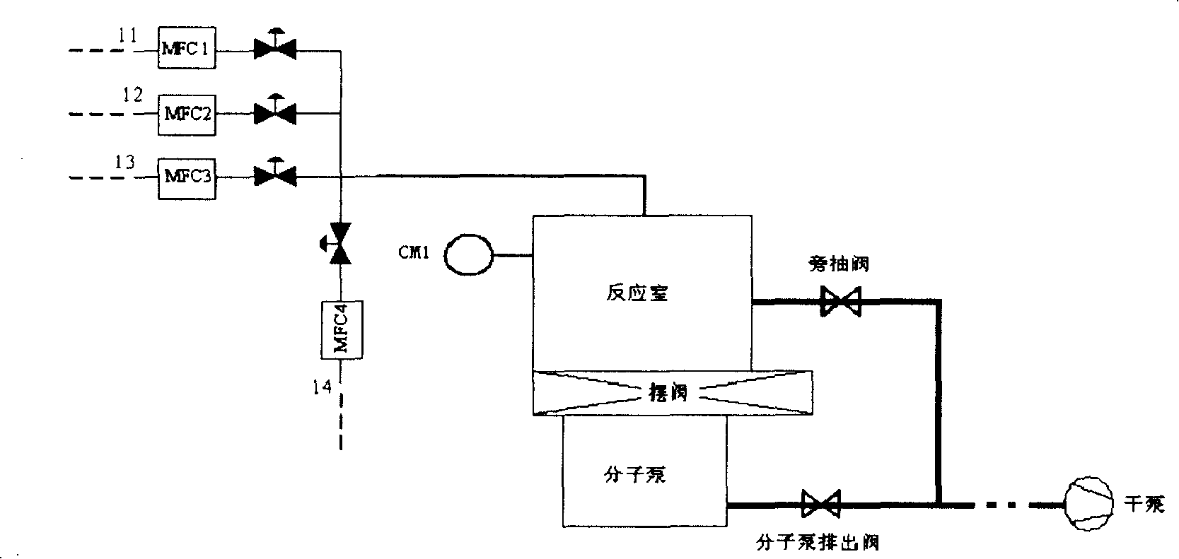
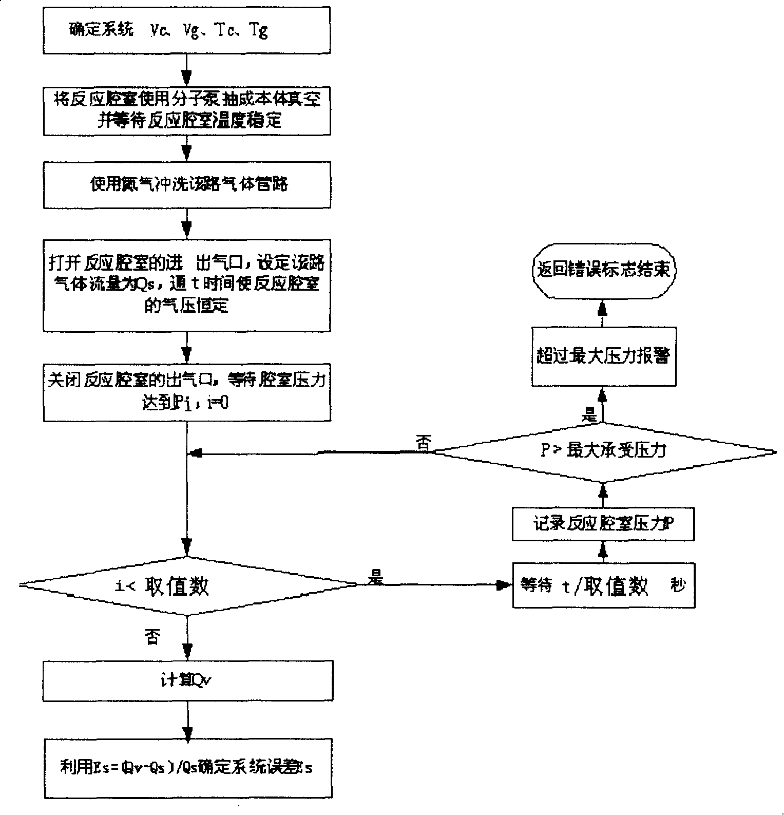
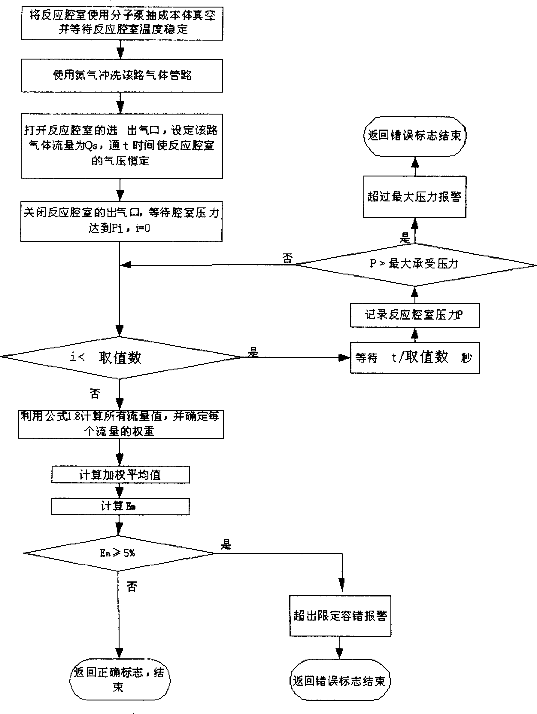

Image

  • Gas flow rate calibrating method
  • Gas flow rate calibrating method
  • Gas flow rate calibrating method

Examples


Embodiment approach

[0074] Its preferred embodiment comprises the following steps:

[0075] Step 11, when the MFC is newly installed in the gas supply system, first measure the inherent error Es of the system, the flow error Em=0 of the newly installed MFC, the method of measurement is:

[0076] Supply gas to the reaction chamber through the gas supply pipeline of the newly installed MFC, measure the change of gas parameters in the gas supply pipeline and the reaction chamber, and calculate the flow rate Qv of the gas through the ideal gas state equation PV=nRT;

[0077] Compare Qv with the set flow value Qs of MFC to get the error of MFC E = Q v - Q s Q s ;

[0078] The inherent error Es=E of the system can be obtained from the formula E=Es+Em;

[0079] Step 12. After the MFC has be...


PUM


Abstract

The invention discloses a calibrating method of air flow used for checking the air flow of an air supply system of a reaction chamber and includes the steps that when the air supply system is newly provided with an air flow controller MFC, the fixed error Es of the system, the volume Vc of the reaction chamber and the volume Vg of an air supply piping are firstly determined, after the MFC is used for a period of time, the flow error Em of the MFC is determined by referring to the Es, the Vc, and the Vg and considering the temperature difference between the reaction chamber and the air supply piping; then the Em value is compared with a limited fault-tolerance value; when the Em value exceeds the limited fault-tolerance value, the system alarms. The invention reduces the system error caused by the difference between the temperature and the volume and reduces the system error by error calibrating. The invention has the advantages of high calculating precision, fast calculating speed as well as convenient and flexible collocation. The invention is mainly applied to calibrating the air flow of the air supply system for a semiconductor processing device and can also be used for calibrating other air supply systems.

Description

technical field [0001] The invention relates to a gas flow calibration method, in particular to a gas flow calibration method of a gas supply system of semiconductor processing equipment. Background technique [0002] In the process of semiconductor silicon wafer processing, the deposition and etching rate of the film depend on the mass flow rate of the process gas entering the reaction chamber and the pressure of the reaction chamber. Every kind of semiconductor silicon wafer processing equipment and different processes require different gas flow ratios. The error of the process gas flow ratio will cause the process to be unstable, and then affect the overall chip yield. Therefore, the accurate measurement and control of process gas flow rate is very important in semiconductor silicon wafer processing equipment. [0003] At present, on the one hand, a high-precision MFC (mass flow controller) is used to measure and control the flow rate of the process gas, and on the othe...

Claims


Application Information

Patent Timeline
Patent Type & Authority Applications(China)
IPC IPC(8): G01F25/00G05D7/06H01L21/00G12B13/00
Inventor 苏晓峰
Owner BEIJING NAURA MICROELECTRONICS EQUIP CO LTD
Why Eureka
Eureka Blog
Learn More