Conical reflecting mirror and device using same

A reflective mirror and cone-shaped technology, applied in the field of reflective mirrors, can solve problems such as complex design of level gauges

Inactive Publication Date: 2008-05-14
QUARTON
View PDF0 Cites 5 Cited by
  • Summary
  • Abstract
  • Description
  • Claims
  • Application Information

AI Technical Summary

Problems solved by technology

Although this method can obtain a reference line with higher brightness, the design of the level tends to be complicated because a motor is required to drive the rotation

Method used


Image

  • Conical reflecting mirror and device using same
  • Conical reflecting mirror and device using same
  • Conical reflecting mirror and device using same

Examples


Embodiment Construction

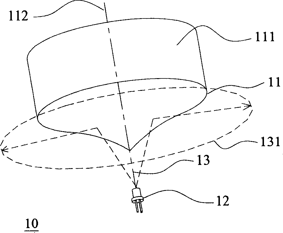
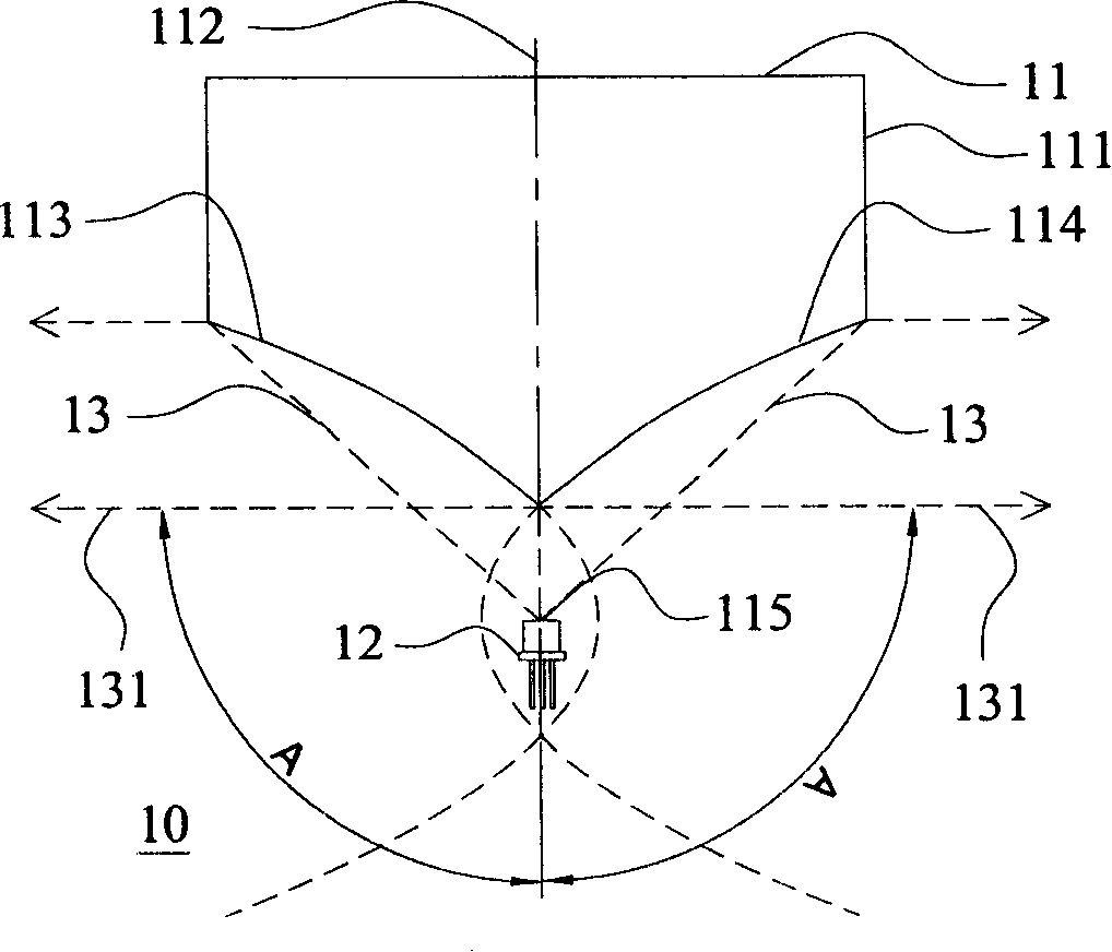
[0015] Please refer to figure 1 and figure 2 As shown, they are respectively a perspective view and a schematic cross-sectional view of a tapered reflector application device according to the first embodiment of the present invention. In the figure, the application device 10 includes a conical reflector 11 and a light source 12 such as a laser diode, wherein the light source 12 does not need to use a collimating lens except for the laser diode, so that the laser beam generated by the laser diode 13. Collimated into parallel laser beams. In addition, when the light source 12 is a diode-pumped solid-state laser (DPSS for short) such as a green laser, the collimator lens in the beam expander can also be omitted, so that the light source 12 produces a diverging laser beam 13.

[0016] The conical reflector 11 is preferably a cylindrical body 111, the central position of the cylindrical body 111 has a reference longitudinal axis 112, and any section around the longitudinal axis...


PUM


Abstract

The invention relates to a taper reflector. The section which winds a vertical axes passing through the body is designed to be two taper curves which respectively extend toward two sides from the vertical axes, and focuses of the two taper curves are overlapped on the vertical axes. Besides, an applying device consists of a taper reflector and a laser diode can spread the beams of light generated by the laser diode to an umbrella-shaped mill finish which has a preset included angle with the vertical axes of the taper reflector.

Description

technical field [0001] The invention relates to a reflector, and in particular to a conical reflector and an application device thereof. Background technique [0002] In engineering fields such as construction and decoration, a level that can project a straight line, a cross line, or various other types of laser light on the target is often used as an auxiliary tool for marking construction reference lines or surfaces. [0003] In order to project a straight line on the target object, a cylindrical lens is usually installed in front of the laser module, so that the parallel laser beam generated by the laser module can be expanded into the required fan-shaped optical surface by the refraction of the cylindrical lens , when the fan-shaped light surface is projected on the target, it will form a line for reference. [0004] Another way is to use a motor to drive the parallel laser beam to rotate, and use the persistence of vision projected by the rotating parallel laser beam o...

Claims


Application Information

Patent Timeline
Patent Type & Authority Applications(China)
IPC IPC(8): G02B5/08H01S5/00
Inventor 陈国禔
Owner QUARTON
Why Eureka
Try Eureka