Swing type ultrasonic vibration drill

An ultrasonic vibration and shaking head technology, which is applied in portable drilling rigs, boring/drilling, drilling/drilling equipment, etc., can solve problems such as poor processing precision, achieve safe operation, broad application prospects, and large application prospects Effect

Inactive Publication Date: 2008-05-14
NANJING UNIV OF AERONAUTICS & ASTRONAUTICS
View PDF0 Cites 2 Cited by
  • Summary
  • Abstract
  • Description
  • Claims
  • Application Information

AI Technical Summary

Problems solved by technology

However, in precision machining, this kind of drill that relies on vibration and impact cutting has a good effect on materials with high hardness and brittleness, but it has a poor effect on materials with relatively high toughness, and the processing precision is poor.

Method used


Image

  • Swing type ultrasonic vibration drill
  • Swing type ultrasonic vibration drill

Examples


Embodiment Construction

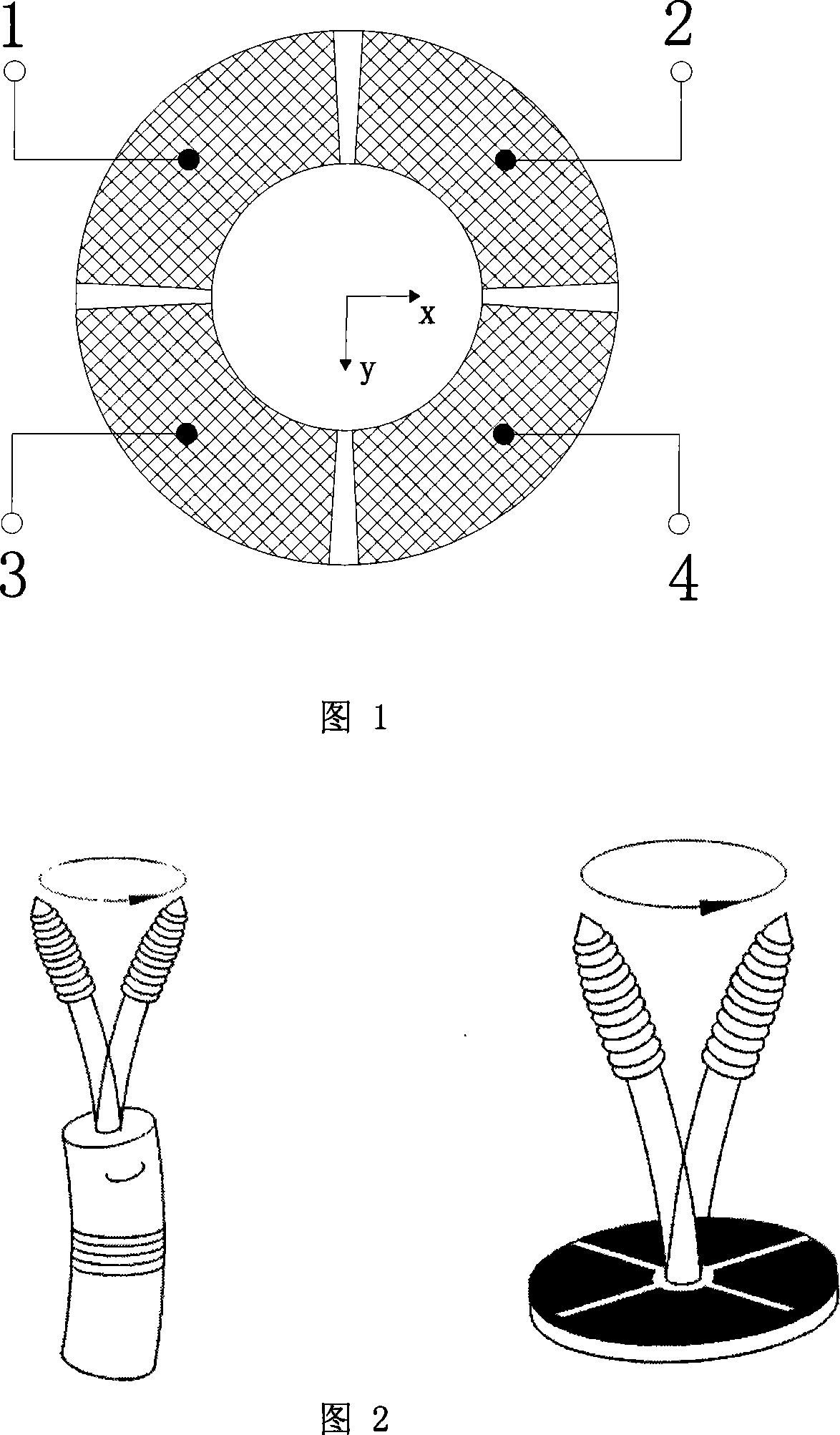
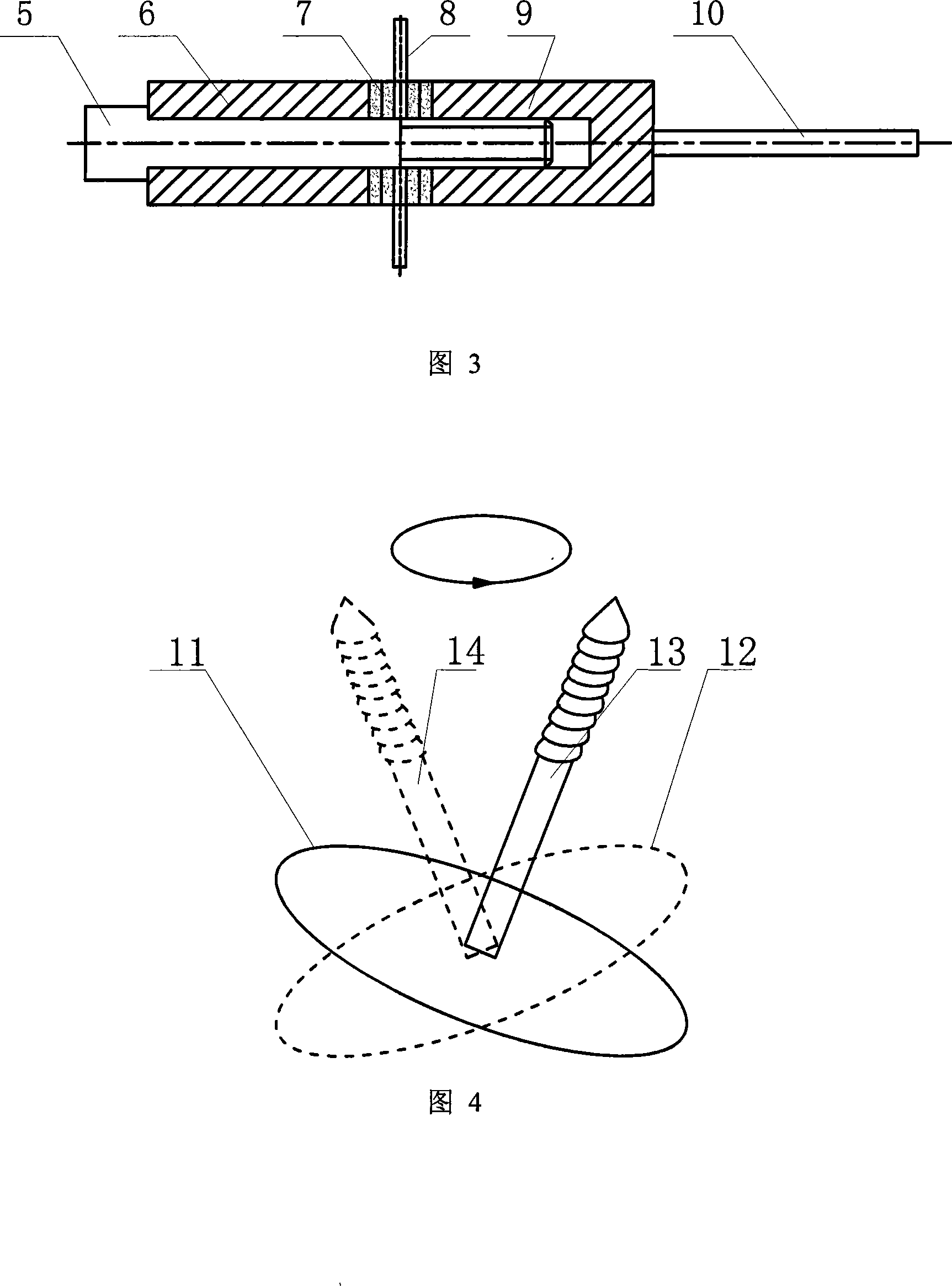
[0017] The working principle and specific implementation of the oscillating head ultrasonic vibration drill will be described below based on the four fan-shaped electrode partitions of the piezoelectric ceramic ring shown in FIGS. 1 to 4 as an example.

[0018] As shown in Figures 1 to 4, the oscillating head ultrasonic vibration drill of the present invention is mainly composed of a stator assembly, a rotor and a drill bit, and is characterized in that: the stator assembly is a piezoelectric ceramic ring polarized in one axial direction 7 is fixed on the stator plate 8, and the stator plate 8 acts as a flange. The first and second stator bodies 6 and 9 are pressed on both sides of the stator plate 8 to provide a certain pre-pressure. The surfaces of the piezoelectric ceramic ring 7 are respectively Four fan-shaped electrodes with even partitions are plated; the stator rod is a rod-shaped rotor, the bottom is fixed near the center of the end of the second stator body, and a dri...


PUM


Abstract

Disclosed is an oscillating ultrasonic vibration drill belonging to the ultrasonic vibration drill field, which comprises a stator component, a rotor and a broach. The stator component comprises a first stator body (6), a second stator body (9), a stator board (8) and a unidirectional polarizing polarized piezoelectric ceramic ring (7) fixed on the stator board, and the rotor is a rod-shaped stator rod connected with the end portion of the second stator body. The surface of the piezoelectric ceramic ring is plated with sector electrodes which are equally partitioned along the circumference. Driving signal is supplied to the piezoelectric ceramic ring through different sector electrodes to facilitate the stator body to generate circumferential traveling wave to drive the stator rod to perform the oscillating movement, thereby realizing the rotating cutting on the end portion of the stator rod. The ultrasonic vibration drill stator rod directly drives the end portion of the stator rod to perform the micrometer amplitude movement to obtain a rotating cutting force, with a high efficiency, an accurate processing, safety and reliability.

Description

Technical field: [0001] The head-shaking ultrasonic vibration drill of the present invention belongs to the field of ultrasonic vibration drills. Background technique: [0002] Power drills are useful for drilling holes in metal, plastic, wood, and other materials and are an essential tool in advanced manufacturing. At present, the basic power of electric drills is almost all traditional electromagnetic motors. The magnetic field generated by electromagnetic motors has adverse effects on some precision instruments. The speed of electromagnetic motors limits its application and promotion in the field of high-speed electric drills. Other power sources are also needed to supplement. The ultrasonic vibration drill currently being studied mainly forms an elliptical motion in the cutting direction to realize the combined impact drilling system of cutting and ultrasonic low-frequency vibration. However, in precision machining, this kind of drill that relies on vibration and impac...

Claims


Application Information

Patent Timeline
Patent Type & Authority Applications(China)
IPC IPC(8): H02N2/00B23B39/10B23B45/02
Inventor 丁庆军金家楣赵淳生
Owner NANJING UNIV OF AERONAUTICS & ASTRONAUTICS
Why Eureka
Try Eureka