Special-purpose gas supplying device for coke dry quenching unit

A technology of gas supply device and CDQ, which is applied in coke oven, petroleum industry, coke cooling, etc. It can solve the problem that it is difficult for the CDQ furnace to reach the designed processing capacity, the coke in the furnace cannot be uniformly cooled, and it is difficult to reach the design capacity. To deal with problems such as capacity, to achieve the effects of non-circulating cooling gas leakage, reasonable structural layout, and flexible adjustment

Active Publication Date: 2008-05-28
ACRE COKING & REFRACTORY ENG CONSULTING CORP DALIAN MCC
View PDF0 Cites 31 Cited by
  • Summary
  • Abstract
  • Description
  • Claims
  • Application Information

AI Technical Summary

Problems solved by technology

However, in the investigation of the 70t / h CDQ device, it is found that the CDQ furnace is difficult to reach its designed processing capacity, and part of the coke produced by the coke oven has to be dehumidified, which is not conducive to the organization of coke oven production, but also Unfavorable for blast furnace operation Coke moisture stability requirements
Compared with foreign large-scale CDQ devices, although the cooling capacity of the CDQ furnace used in the design of the 70t / h CDQ device and the gas-to-material ratio per ton of coke are both extremely large, because the coke in the furnace is in the entire cross-section of the CDQ furnace On the other hand, uniform cooling cannot be achieved and the temperature of the cold circulating gas entering the CDQ furnace is high, which greatly prolongs the cooling time required for the coke in the furnace. Even if the circulating air volume is increased in actual production, it is difficult to reach the design processing capacity

Method used


Image

  • Special-purpose gas supplying device for coke dry quenching unit
  • Special-purpose gas supplying device for coke dry quenching unit
  • Special-purpose gas supplying device for coke dry quenching unit

Examples


Embodiment Construction

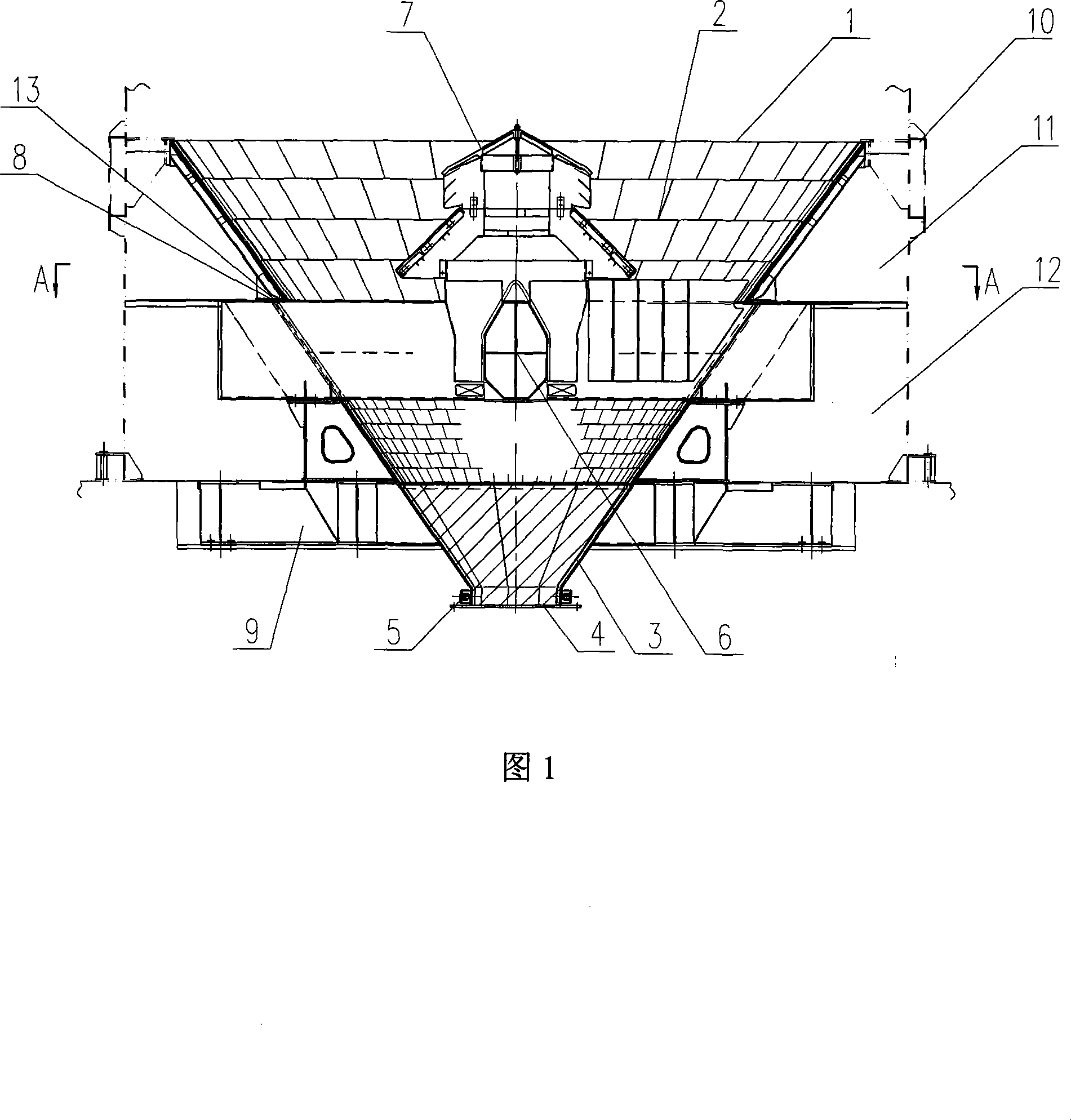
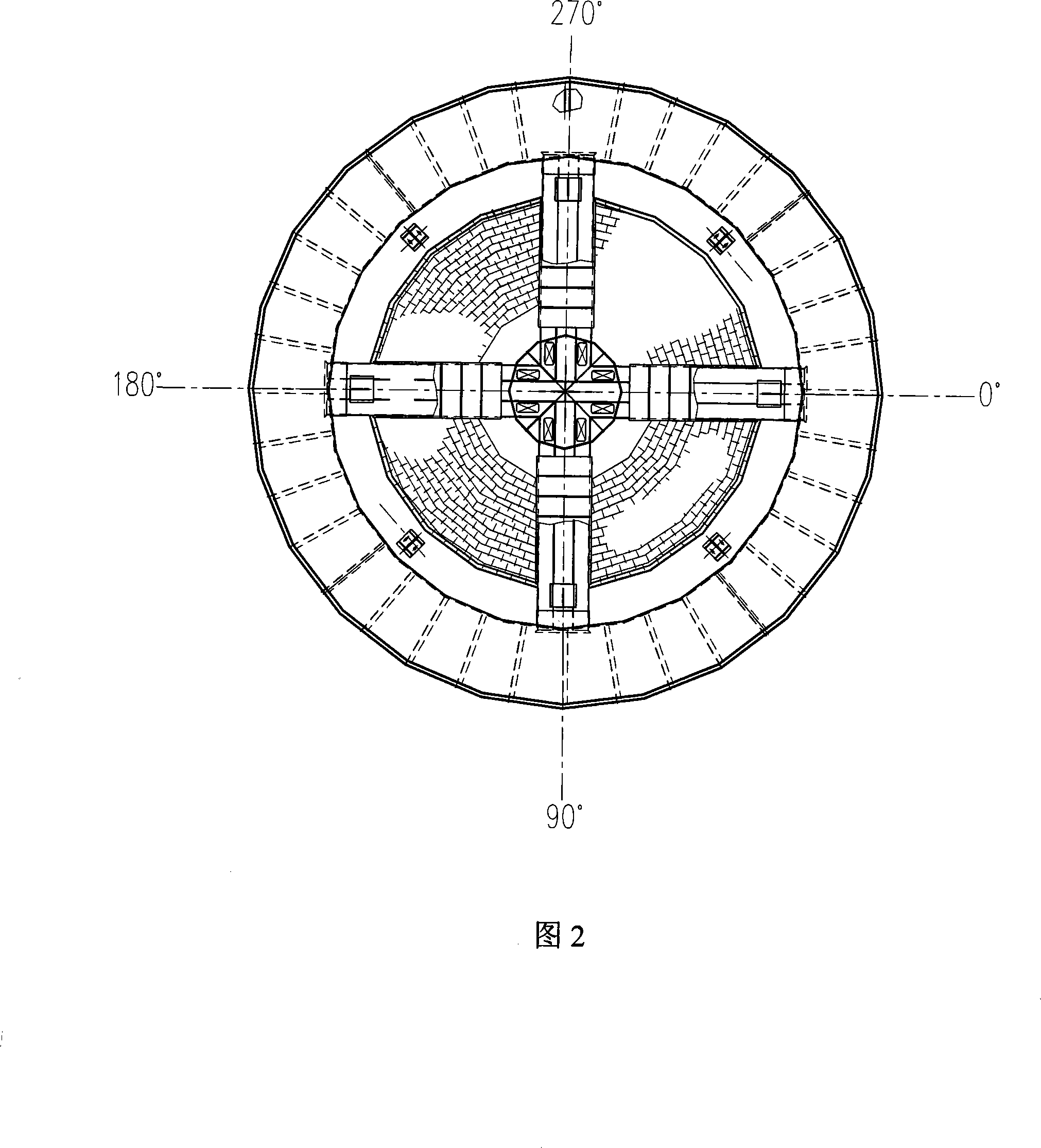
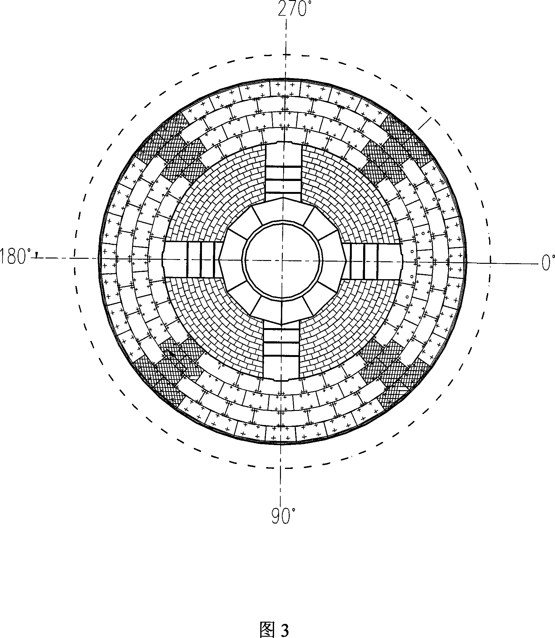
[0019] The present invention will be described in detail below in conjunction with the accompanying drawings.

[0020] See Figure 1, Figure 2, Figure 3, and Figure 4. The device consists of an upper cone bucket 1, a lower cone bucket 3, a CDQ furnace shell 10, an annular air duct 13, a cross air duct 6, and a central air cap 7. The upper cone Bucket 1 and lower cone bucket 3 are inserted together, and the annular gap formed by the sleeve inserting eaves forms an annular air duct 13, and an air volume regulating plate is provided at this place, and its air volume control is completed by the air volume regulating plate 8. The cross air duct 6 is located on the upper part of the lower cone 3 and is set horizontally. Its center coincides with the center of the CDQ and extends upward to communicate with the central wind cap 7 arranged on the upper part of the cone; the upper cone 1 and the lower cone 3 are connected to the CDQ The gas distribution chamber composed of the casing 10 ...


PUM


Abstract

The invention relates to an air supply facility specially used for a dry out furnace. The facility is composed of an upper cone funnel, a lower cone funnel, a dry out furnace casing body, a ring-shaped air channel, a cross air channel, and a central windshield, wherein the upper cone funnel and the lower cone funnel are sleeved and inserted with each other, the ring-shaped air channel is composed of an annular gap which is formed by a sleeve and inserting ledge, and the cross air channel is positioned on the upper portion of the lower cone funnel and is horizontally arranged, the centre of the cross air channel coincides with the centre of the dry out furnace and extends upwards and is communicated with the central windshield which is arranged on the cone funnel, the facility employs a combining air supply form of that peripheral air rings supply air from outside in and the central windshield supplies air from inside out on the upper portion of the furnace body. The facility can effectively resolve the problem that the cooling cycle air entering the dry out furnace is uniformly distributed in the periphery direction of the dry out furnace, which is favorable for achieving uniform cooling of the coke in the furnace, thereby improving the cooling property of the dry out furnace, increasing the cooling efficiency of the dry out furnace, and reducing the dry out time of the coke in the dry out furnace.

Description

technical field [0001] The invention relates to a special equipment for cooling the coke in the CDQ furnace, which can effectively and evenly exchange heat between the circulating cooling gas and the coke, and enable the cold coke to pass through the CDQ furnace evenly. It is a special gas supply for the CDQ furnace. device. Background technique [0002] There are only 75t / h gas supply device for CDQ and 70t / h gas supply device for CDQ operating in China, both of which have relatively small processing capacity. The gas supply device for 75t / h coke CDQ has achieved good results through continuous improvement during use. However, in the investigation of the 70t / h CDQ device, it is found that the CDQ furnace is difficult to reach its designed processing capacity, and part of the coke produced by the coke oven has to be dehumidified, which is not conducive to the organization of coke oven production, but also It is not conducive to the requirement of coke moisture stability fo...

Claims


Application Information

Patent Timeline
Patent Type & Authority Applications(China)
IPC IPC(8): C10B39/02
Inventor 陈海文王明登张长青陈健伟魏振东
Owner ACRE COKING & REFRACTORY ENG CONSULTING CORP DALIAN MCC
Why Eureka
Try Eureka