
Purification device for decreasing particulate matter and nitrogen oxides in diesel engine

A technology of nitrogen oxides and purification devices, which is applied to the electronic control of noise reduction devices, exhaust devices, and exhaust treatment devices, and can solve problems such as complex structures

Inactive Publication Date: 2008-05-28
HYUNDAI MOTOR CO LTD
View PDF1 Cites 16 Cited by
  • Summary
  • Abstract
  • Description
  • Claims
  • Application Information

AI Technical Summary

Problems solved by technology

However, there is a problem in that, depending on the conditions of the exhaust gas, the diesel fuel decomposition catalyst (DFC) is rapidly oxidized, with the result that purification of the exhaust gas occurs by oxidizing the fuel, not by decomposing the fuel injected from the secondary injection system, thereby forming Phenomenon of reducing agent to purify exhaust gas
[0008] Moreover, there is a problem in that the structure of the conventional purifying device is complicated in that it is equipped with an additional branch pipe branching from the exhaust pipe in front of the catalytic diesel particulate filter (CDPF) and passing the nitrogen The front of the oxide adsorption catalyst (de-NOx catalyst) includes the outlet, and the diesel fuel decomposition catalyst (DFC) is included in the branch pipe

Method used


Image

  • Purification device for decreasing particulate matter and nitrogen oxides in diesel engine
  • Purification device for decreasing particulate matter and nitrogen oxides in diesel engine

Examples


no. 1 approach

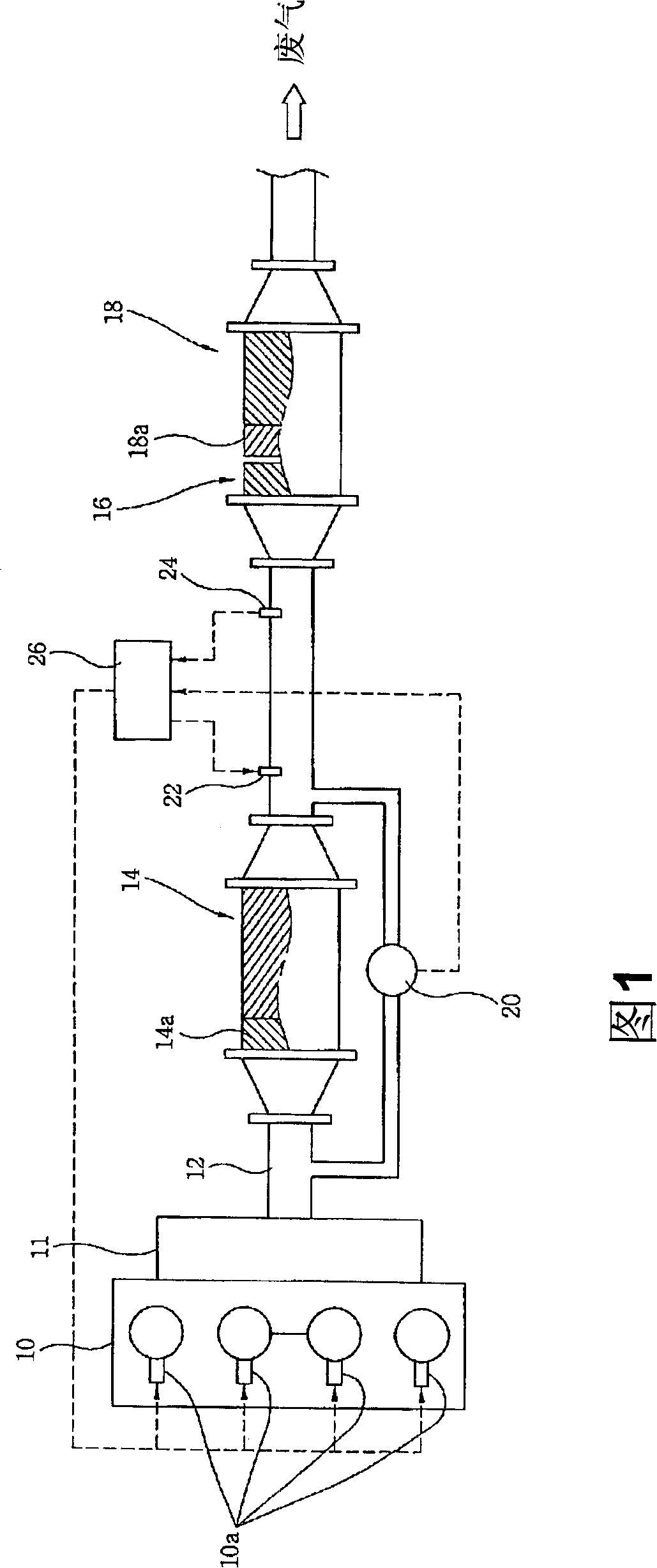
[0038] Also, in the present invention, based on the exhaust path, the diesel fuel decomposition catalyst (DFC) 16 is located at the upstream end of the nitrogen oxide adsorption catalyst (de-NOx catalyst) 18, and the catalytic diesel particulate filter (CDPF) 14 is located at the nitrogen oxidation The upstream end of the substance adsorption catalyst (de-NOx catalyst) 18. According to the first embodiment of the present invention, a catalyzed diesel particulate filter (CDPF) 14 is disposed in front of a diesel fuel decomposition catalyst (DFC) 16 .

[0039] In this case, a diesel fuel decomposition catalyst (DFC) 16 and a nitrogen oxide storage catalyst (de-NOx catalyst) 18 are sequentially arranged in the same housing.

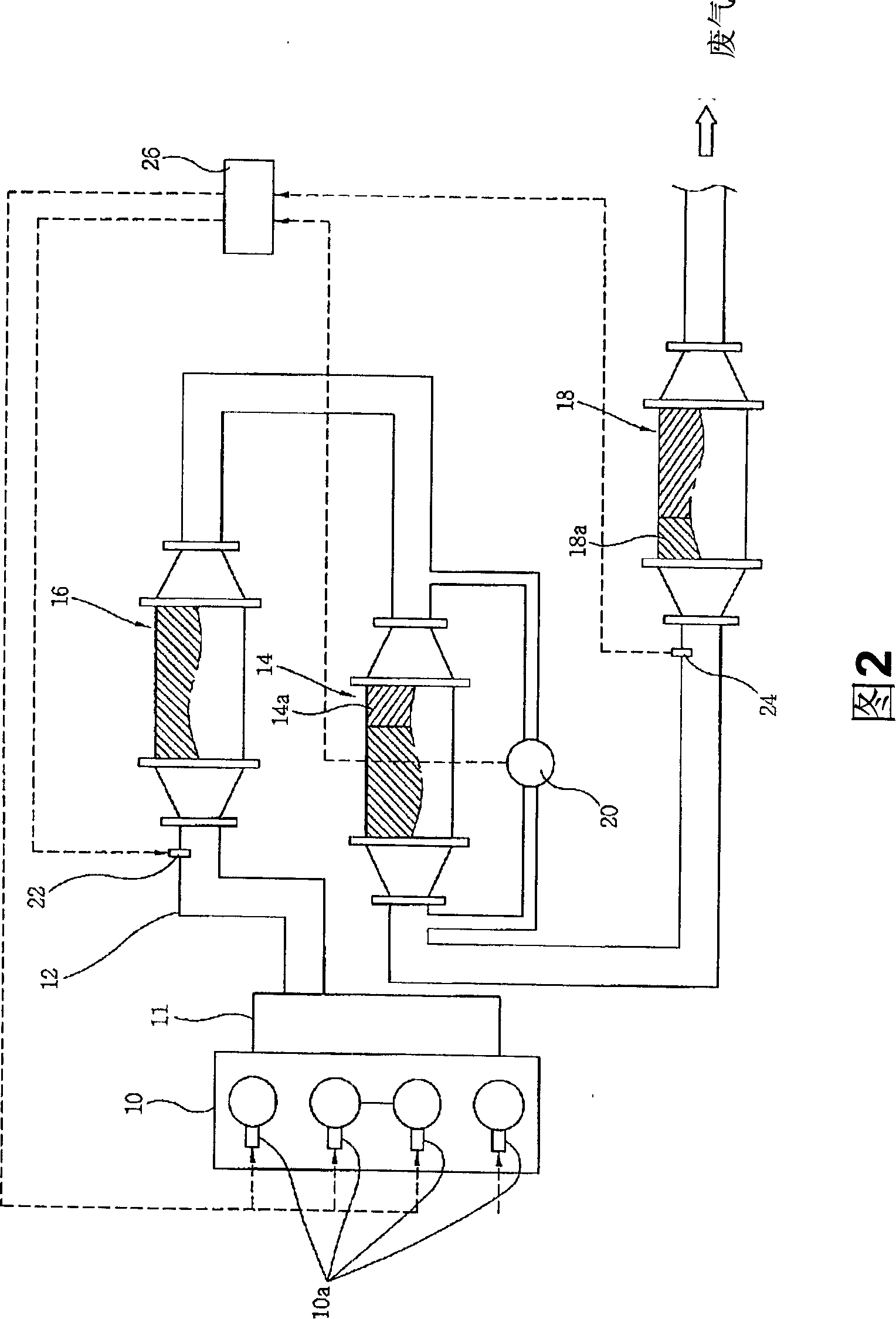
[0040] Referring to Figure 2, a second embodiment of the present invention is shown. According to the second embodiment, a diesel fuel decomposition catalyst (DFC) 16 is provided upstream of a catalyzed diesel particulate filter (CDPF) 14 based on the exhau...

Embodiment approach

[0042] Furthermore, according to the first and second embodiments of the present invention, the post-injection injector 22 is located on the exhaust pipe 12 in front of the diesel fuel decomposition catalyst (DFC) 16, and the nitrogen oxide sensor 24 is located on the nitrogen oxide adsorption catalyst (de- NOx catalyst) 18 on the exhaust pipe 12 ahead.

[0043] In this case, the nitrogen oxide sensor 24 detects the amount of nitrogen oxides (NOx) contained in the exhaust gas flowing through the exhaust pipe 12 in real time, and then outputs it to the control device 26 . The control device 26 estimates the amount of nitrogen oxides (NOx) accumulated in the nitrogen oxide adsorption catalyst (de-NOx catalyst) 18 by inputting signals from the nitrogen oxide sensor 24, and converts the amount of the accumulated nitrogen oxides (NOx) to The amount is compared with the capacity of the nitrogen oxide storage catalyst (de-NOx catalyst) 18, and then the regeneration time of the nitrog...


PUM


Abstract

A purification device is disclosed for a reduction in the amount of particulate matter and nitrogen oxides. The device comprises a catalytic diesel particulate filter (CDPF), a differential pressure transducer, a rearward injector, diesel fuel decomposition catalysts (DFC), nitrogen oxides absorption catalysts (de-NOx catalysts), a nitrogen oxide sensor and a controlling device.

Description

[0001] Cross References to Related Applications [0002] This application is based on and claims priority from Korean Application No. 10-2006-0115167 filed on November 21, 2006, which is hereby incorporated by reference in its entirety. technical field [0003] The invention relates to a purification device for reducing particulate matter and nitrogen oxide contained in exhaust gas of a diesel engine. Background technique [0004] Generally, in conventional purification devices for reducing particulate matter and nitrogen oxides contained in diesel engine exhaust gas, a catalytic diesel particulate filter (Catalyzed Diesel Particulate Filter) (CDPF), a nitrogen oxide adsorption catalyst (de-NOx catalyst) and a diesel engine The oxidation catalyst (DOC) is arranged in the exhaust pipe in sequence, and the auxiliary exhaust pipe branched from the exhaust pipe is arranged in front of the catalytic diesel particulate filter (CDPF) in the exhaust pipe, the switch valve, the secon...

Claims


Application Information

Patent Timeline
Patent Type & Authority Applications(China)
IPC IPC(8): F01N3/025F01N9/00F01N3/28
CPCF01N2610/03F01N3/0871F01N3/035F01N2560/08F01N13/02F01N3/0821F01N2560/026F01N13/009F01N3/00F01N3/02F01N3/08F01N3/20
Inventor 李津夏
Owner HYUNDAI MOTOR CO LTD
Learn More