Improved flywheel design with vibration-reducing and damping device

A damping device, an improved technology, applied in the direction of flywheel, spring/shock absorber, vibration suppression adjustment, etc., can solve the problems of weak anti-shock, anti-vibration ability, heavy weight, etc., to achieve improved anti-vibration ability and simple structure , The effect of improving the overall reliability

Active Publication Date: 2010-08-11
LUOYANG BEARING RES INST CO LTD
View PDF0 Cites 3 Cited by
  • Summary
  • Abstract
  • Description
  • Claims
  • Application Information

AI Technical Summary

Problems solved by technology

[0002] The flywheel body is the output mechanism of the angular momentum in the momentum wheel. Therefore, the flywheel body in the momentum wheel is generally designed as a high-efficiency structure, and try to produce a larger moment of inertia with a smaller mass, that is, the ratio of the mass of the flywheel to the moment of inertia is smaller; Most of the flywheel body adopts a plate-type-circular plate-supported rim or a spoke-spoke-supported rim structure; traditionally, a wide-plate or spoke-type flywheel is processed from a whole blank through turning, milling and other processes. The resulting flywheel body is a rigid whole without any vibration damping device; therefore, under the same conditions, compared with the spoke structure, the spoke plate type has a stronger ability to resist shock and vibration, but the overall weight is too large; The overall weight of the spoke type is lighter, but the ability to resist shock and vibration is weak

Method used


Image

  • Improved flywheel design with vibration-reducing and damping device
  • Improved flywheel design with vibration-reducing and damping device
  • Improved flywheel design with vibration-reducing and damping device

Examples


Embodiment Construction

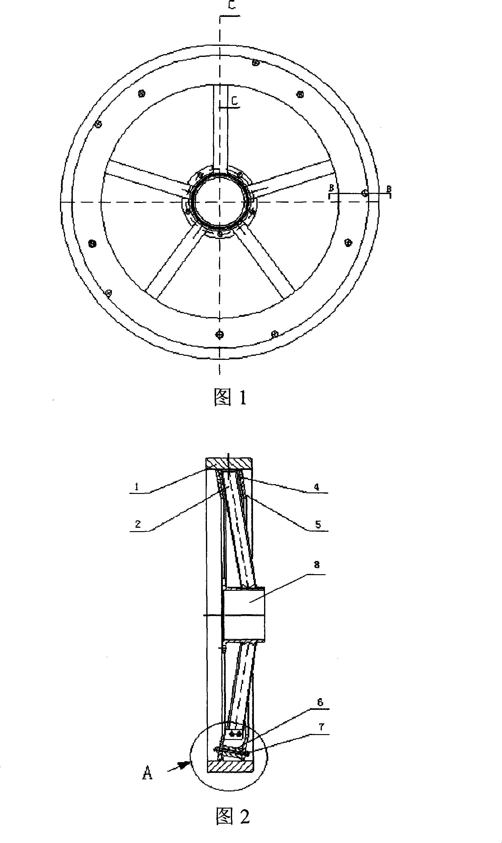
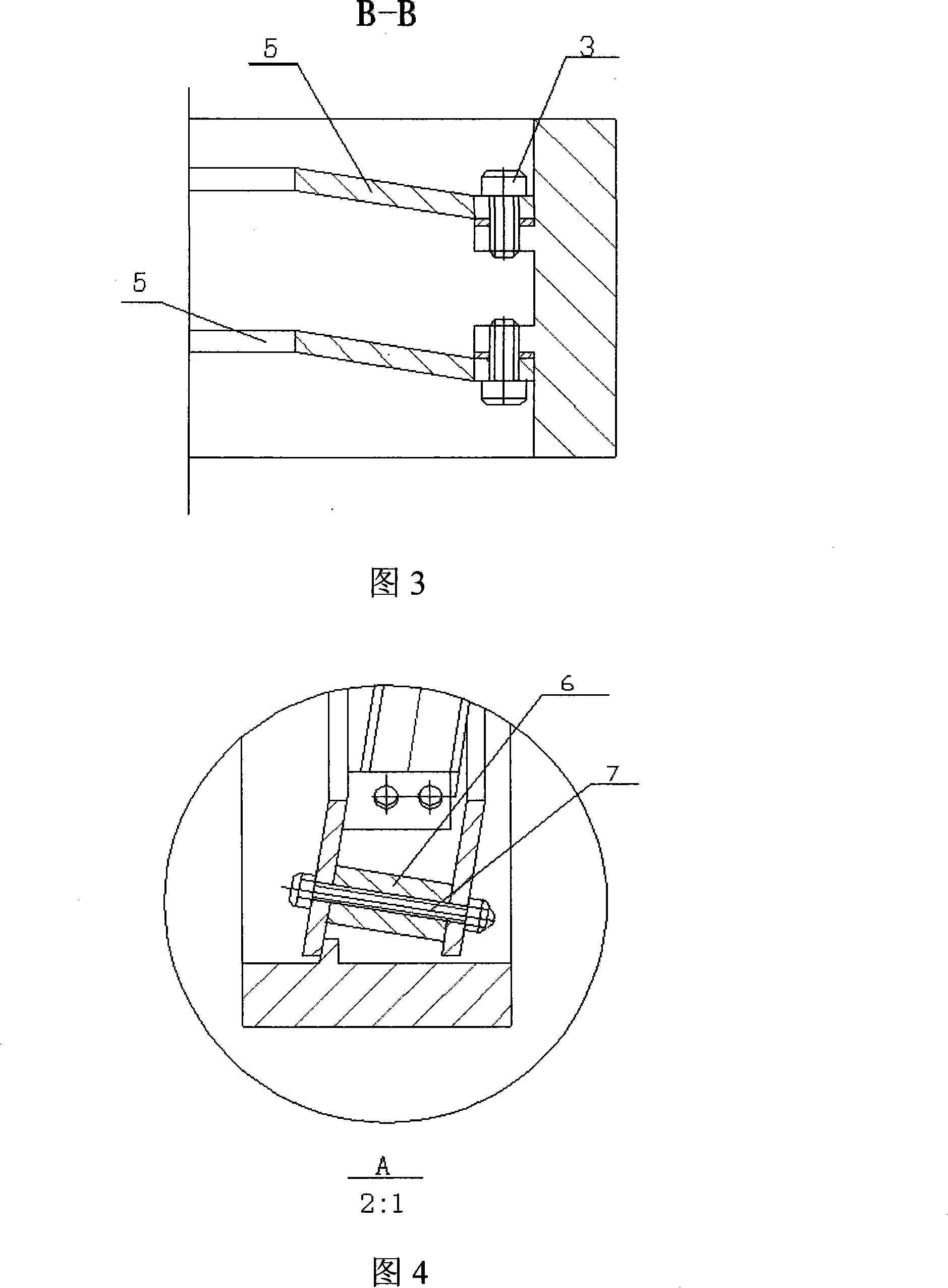
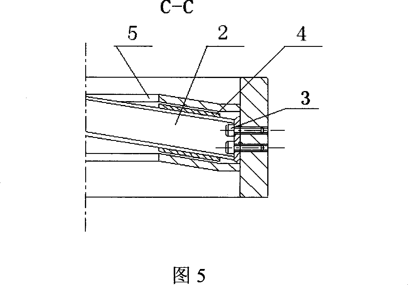
[0018] The design of the improved flywheel body with vibration damping device of the present invention adopts five I-shaped spokes of smaller mass to support the wheel rim of larger mass in the design method of the flywheel body, and strives to obtain the maximum moment of inertia under limited conditions , improve the rigidity of the flywheel support system and reduce the overall weight; considering that the flywheel body vibrates under the external force, the wheel rim will drive the spokes to vibrate axially and vibrate, so friction is added to the spokes The friction plate and the damping ring, the friction plate will be in contact with the damping ring, this contact is either an instantaneous elastic collision, or friction, both elastic collision and friction will absorb a large amount of vibration energy, thus effectively attenuating the vibration generated by the external force Effect; the vibration reduction effect of damping can be controlled by changing the gap betwee...


PUM


Abstract

An improved type flywheel body design which has a vibration damping attenuation device comprises a wheel rim (2), H-shaped spokes (2), screws (3), friction wafers (4), damping rings (5), a supporting muff (6), bolts (7) and a hub (8), wherein five H-shaped spokes are separated according to the same angle to weld with the hub, and are fixed with wheel edges through screws to form an improved type flywheel body, two damping rings are fixed on small ten blocks which are separated by five H-shaped spokes on the internal diameter walls of the wheel edges, the two damping rings are fixed with the screws in a cantilever shape and are respectively arranged on the upper portion and the lower portion of the spokes, the relative space between the two damping rings are decided by the length of the supporting muff and are fixed through the bolts, the friction wafers are arranged between the damping ring and each spoke, and are bonded on the beam surface of the spoke to form a certain gap between the damping rings, and the size of the gap is decided by vibration acceleration value. When vibrated, elastic collision or friction is formed between the friction wafer and the damping ring, which reduces extraneous vibration, and the vibration damping effect is significant.

Description

technical field [0001] The invention belongs to the technical field of mechanical vibration and friction, in particular to an improved design of a flywheel body with a vibration damping device. Background technique [0002] The flywheel body is the output mechanism of the angular momentum in the momentum wheel. Therefore, the flywheel body in the momentum wheel is generally designed as a high-efficiency structure, and try to produce a larger moment of inertia with a smaller mass, that is, the ratio of the mass of the flywheel to the moment of inertia is smaller; Most of the flywheel body adopts a plate-type-circular plate-supported rim or a spoke-spoke-supported rim structure; traditionally, a wide-plate or spoke-type flywheel is processed from a whole blank through turning, milling and other processes. The resulting flywheel body is a rigid whole without any vibration damping device; therefore, under the same conditions, compared with the spoke structure, the spoke plate ty...

Claims


Application Information

Patent Timeline
Patent Type & Authority Patents(China)
IPC IPC(8): F16F15/30F16F15/139
Inventor 臧稳通郭向东高飞姜维李建华窦庆敏
Owner LUOYANG BEARING RES INST CO LTD
Why Eureka
Try Eureka