Eureka AIR delivers breakthrough ideas for toughest innovation challenges, trusted by R&D personnel around the world.

Powdered fuel cell

A fuel cell and powder technology, applied in fuel cells, fuel cell additives, fuel cell components, etc., can solve problems such as bulky, inconvenient, and low energy efficiency

Inactive Publication Date: 2008-05-28
林益泉
View PDF11 Cites 2 Cited by
  • Summary
  • Abstract
  • Description
  • Claims
  • Application Information

AI Technical Summary

Problems solved by technology

[0015] 2. Low energy density: In theory, a kilogram of hydrogen storage material is only about 1.5WT%, which is expensive or uses high-pressure hydrogen or liquid hydrogen, and the energy density is lower
[0016] 3. Safety: very dangerous, hydrogen burns fast, flammable and explosive
[0017] 4. Low energy efficiency: only 30% to 60% efficiency
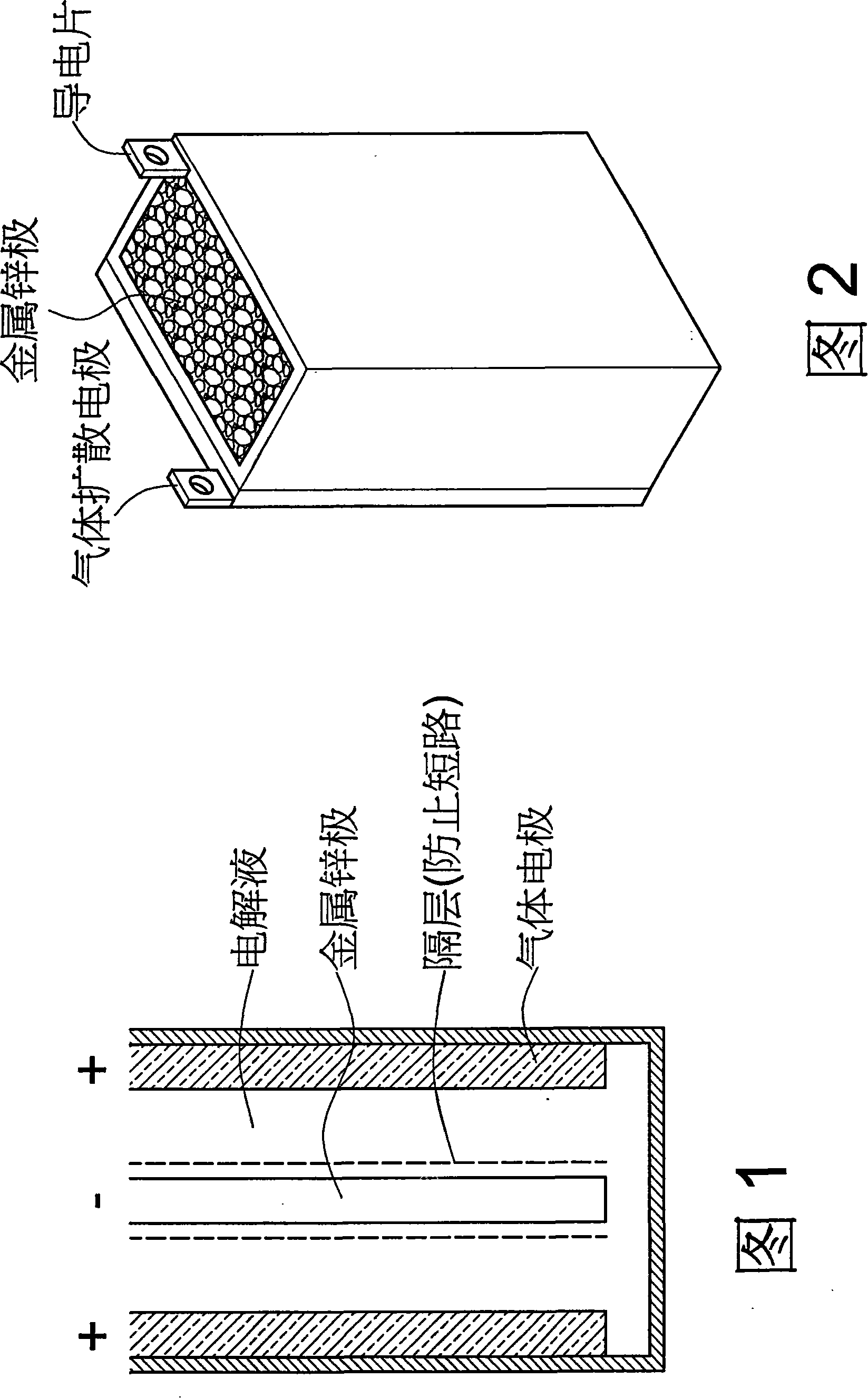
[0031] In the commercial metal-air batteries used today, although the price is low, they are bulky and have low energy density. To replenish power, the entire battery needs to be replaced or recharged. It cannot be completely consumed every time it is used, and 10% to 20% will remain unoxidized , a waste of electricity, affecting the efficiency is extremely inconvenient, and another obstacle of the metal-air fuel cell is the management of air (oxidant) and heat and the inherent volume expansion of the metal. The expansion of the zinc electrode is the oxidation of metal zinc to zinc oxide and zinc hydroxide Because the specific gravity of zinc powder is 7.14 and the specific gravity of zinc oxide is 5.06, due to the different specific gravity, the volume of zinc powder will expand after oxidation, resulting in electrolyte overflow and the bending of the anode is the volume oxidized by metal zinc Another obstacle of metal-air fuel cells is the battery failure caused by the deterioration of the anode, and uneven discharge will reduce the output power of the battery, so it is difficult to replace gasoline

Method used


Image

  • Powdered fuel cell
  • Powdered fuel cell
  • Powdered fuel cell

Examples


Embodiment Construction

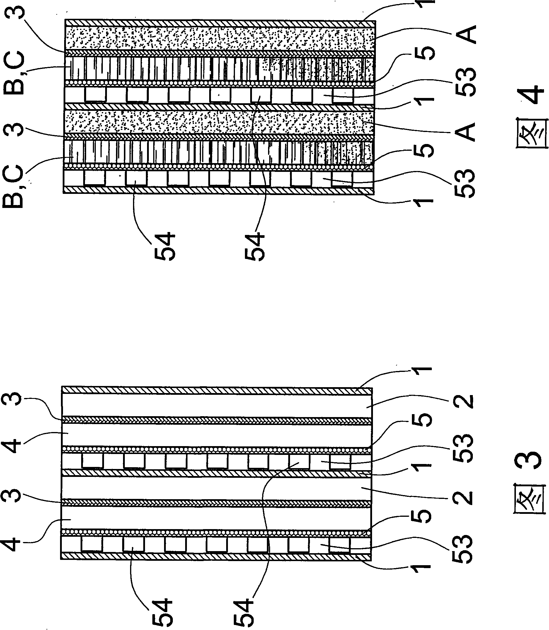
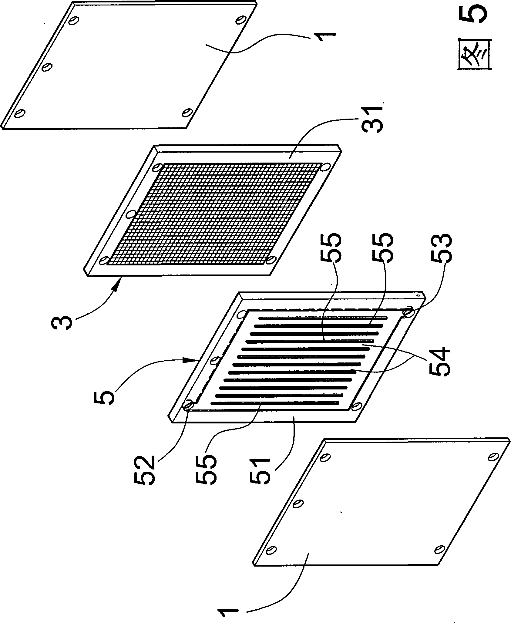
[0064] Please refer to Fig. 3, the top view of the combination of the powdered fuel cell provided by the present invention mainly includes: the current collector 1 is made of conductive material for collecting electron conduction; the fuel chamber 2 provides a storage space for the powdery fuel A , to carry out the battery oxidation reaction; the porous diaphragm 3, which provides the oxide B after the reaction of the powdery fuel A to pass through, and blocks the unreacted powdery granular fuel A, and its porous diaphragm 3 is provided with a plurality of holes , and the oxide B passes through the hole to the electrolyte chamber 4 described later; the electrolyte chamber 4 provides a storage space for the electrolyte C to conduct ions, and provides a collection space for the reacted oxide B; and the gas At least one side of the diffusion electrode 5 is formed to catalyze the entry and exit of the oxidant, so as to obtain electron and ion conduction.

[0065] For a more detail...


PUM


Abstract

A powdered fuel cell includes current collectors, fuel chambers, porous membranes, electrolyte chambers and gas diffusion electrodes. The porous membranes pass oxide the formed from the reacted fuel through the holes thereof and block the unreacted powdered fuel; the electrolyte chambers provide the storage space for electrolyte so as to conduct ions and provide the collection space for the reacted oxide; and the gas diffusion electrodes, each has one side surface thereof for an oxidizing agent incoming and outgoing and catalyzed to acquire electron and ion conduction, wherein one of the current collectors and one of the gas diffusion electrodes are connected by posts, saving outer wires and being connected directly to the anode and the cathode as a loop. Thus, a power supply being capable of electricity conversion and storage and movable is realized.

Description

technical field [0001] The invention relates to a powder fuel cell, in particular to a powder fuel cell with low cost, high energy density and high efficiency, which can reduce weight and energy consumption. Background technique [0002] The ability to convert chemical energy into electrical energy and back is well known, however some applications such as electric vehicles require high energy density, high energy conversion efficiency, low cost, long-term life safety, convenience, and environmental impact , are all factors that need to be considered for batteries for many applications during production. In general, it will increase the weight and volume of the general battery composition. Therefore, it is difficult to build a commercially practical battery that is operable, safe and convenient. . [0003] A fuel cell is an electrochemical device in which part of the energy of a chemical reaction is directly converted into direct current energy. The direct conversion of ene...

Claims


Application Information

Patent Timeline
IPC IPC(8): H01M8/00
CPCH01M8/065H01M8/225H01M8/04201H01M2008/1095H01M8/0273H01M8/0297H01M8/0289H01M8/2455Y02E60/50H01M8/02H01M8/0258
Inventor 林益泉
Owner 林益泉
Why Eureka
Eureka Blog
Learn More