Method of preparing container roof plate

A manufacturing method and container technology, applied in the direction of manufacturing tools, other manufacturing equipment/tools, feeding devices, etc., can solve the problems of scattered production equipment layout, low equipment utilization rate, large workshop area, etc., to achieve automatic production and improve Production efficiency and the effect of reducing the floor space

Active Publication Date: 2008-06-04
CHINA INTERNATIONAL MARINE CONTAINERS (GROUP) CO LTD
View PDF0 Cites 15 Cited by
  • Summary
  • Abstract
  • Description
  • Claims
  • Application Information

AI Technical Summary

Problems solved by technology

[0006] Low utilization rate of equipment and low production efficiency;
[0007] 2. Workers need to carry out multiple handling and loading and unloading operation

Method used


Image

  • Method of preparing container roof plate
  • Method of preparing container roof plate
  • Method of preparing container roof plate

Examples


Embodiment 1

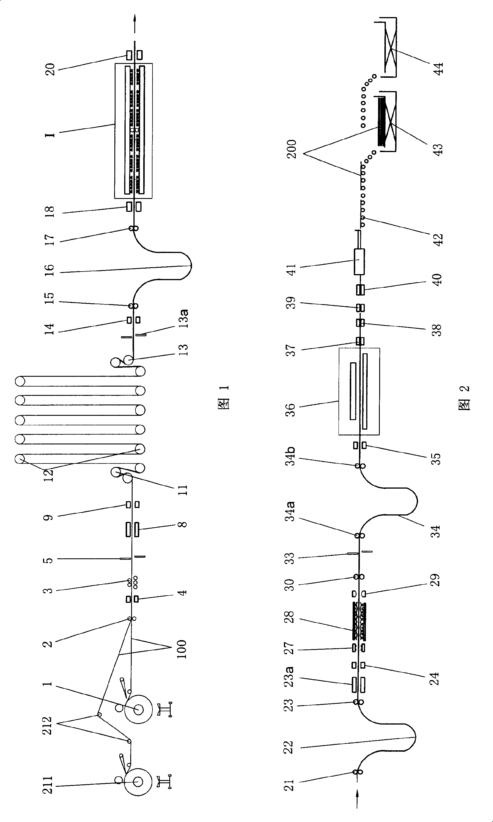
[0060] Fig. 1 and Fig. 2 show the schematic diagram of the production line of Embodiment 1 of the manufacturing method of the container roof according to the present invention. As shown in Figure 1 and Figure 2, the production line equipment of this embodiment is arranged as follows:

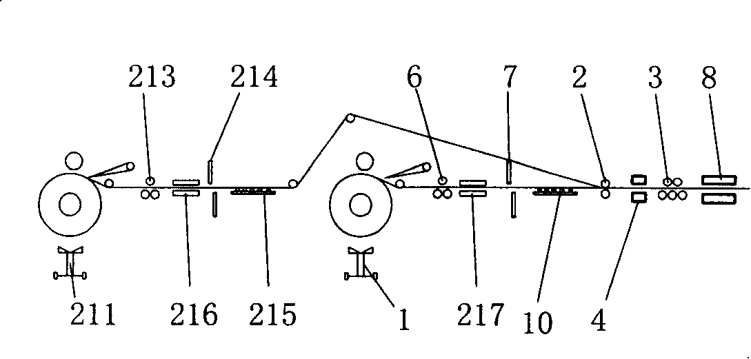
[0061] Two sets of uncoiling equipment and one set of leveling equipment are used for coil uncoiling and leveling. The two sets of uncoiling equipment are arranged successively along the steel plate conveying direction. The leveling equipment is a steel plate leveler 3 arranged behind the uncoiler 1 . The continuous steel plate 100 output by the subsequent uncoiler 211 is guided by a steel plate guiding device 212 (guide rollers, guide wheels, etc. can be used).

[0062] Before the steel plate leveling machine 3, a pinch roller 2 and a plate centering device 4 are arranged to feed and center the continuous steel plate 100. Behind the steel plate leveling machine 3, a steel plate shearing devic...

Embodiment 2

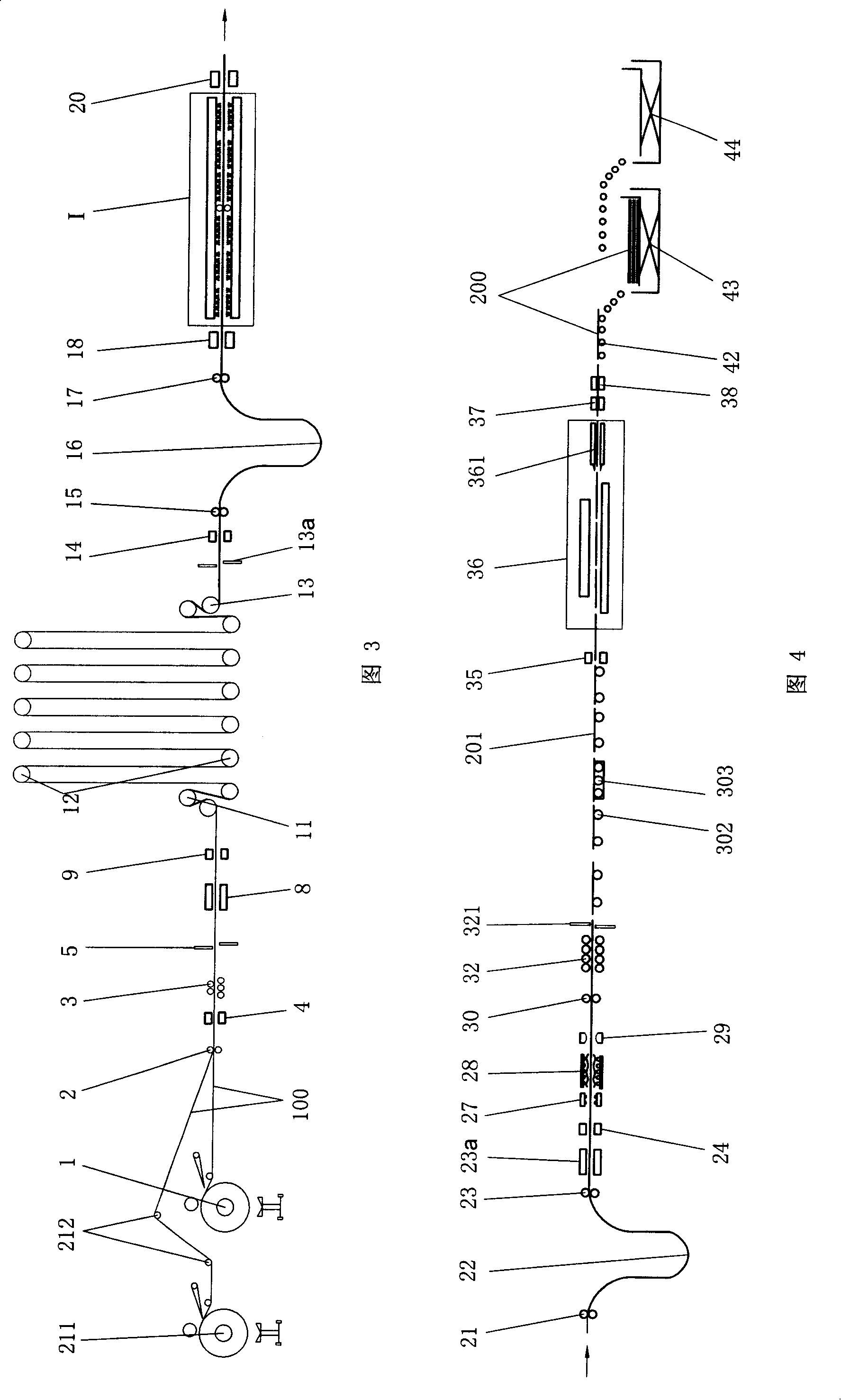
[0107] Fig. 3 and Fig. 4 show the schematic diagrams of the production line of Embodiment 2 of the manufacturing method of the container roof of the present invention. As shown in Fig. 3 and Fig. 4, the equipment layout and functions of the production line of this embodiment are generally the same as those of the embodiment, the difference is that after the pinch roller 30, a sheet material positioning and shearing device 321 (such as a positioning shearing machine) is arranged successively or other sheet material positioning and cutting equipment), sheet material conveying device 302 (such as conveying roller table, belt conveying device, etc.), sheet material conveying device 302 includes driving roller 303, and sheet material conveying device 302 conveys the sheet material 201 after cutting Before the roll forming equipment 36 , a sheet material centering device 35 is provided in front of the press forming equipment 36 to ensure that the sheet material 201 is centered and en...


PUM


Abstract

The invention relates to a container top plate fabrication method, comprising processes of coiling and leveling of coiled plates, after the centering, storage and traction after storage of continuous steel plate which is leveled, continuous blasting of the two surfaces of the continuous steel plate, continuous painting disposal of the two surfaces of the continuous steel plate, continuous drying, traction before the storage of the continuous steel plate, storage and traction after storage, centering the continuous steel plate, pressing and forming a top plate, edging, size fixing and cutting into single top plate which is then conveyed to finished product collection and transfer device for collection and transfer storage. The invention has the advantages of implementing the automatic production of the container top plate, reducing the occupying area of equipment, the mounting content of the equipment and the number of required workers, improving production efficiency and the utilization ratio of the equipment, greatly reducing the labor intensity of workers and having determining meaning for improving the technical level of container production and reducing production cost.

Description

technical field [0001] The invention relates to a method for manufacturing container parts, more specifically, to a method for manufacturing a container roof. Background technique [0002] The roof is an important part of the container. At present, the container roof is manufactured using the following production process: "uncoiling leveling - fixed length cutting - stacking - hoisting to the shot blasting (sanding) pretreatment line - loading - shot blasting (sanding) pretreatment Processing—primer spraying—drying—unloading and stacking—levelling (if necessary), hoisting to the press line—feeding—pressing—stacking—feeding—trimming—stacking.” [0003] The above-mentioned existing container roof production process method is to uncoil the steel plate and cut it in sections first, then carry out sandblasting, painting and drying pretreatment on each plate respectively, and then carry out pressing and trimming respectively Therefore, in the process of processing, the sheet mat...

Claims


Application Information

Patent Timeline
IPC IPC(8): B23P23/04B21D22/00B21D43/00B21D43/08B21D43/12B21D43/20B21D43/22B21D43/28B21D1/00B23Q7/00B65G57/00B65G29/00B24C1/00B05C9/04B05D1/02B05D1/40B05D3/00
Inventor 刘学斌李成明郭雷黄素辉芦兰庆梁尚富张寿超温廷及李海明李建平汪德禄朱鹏飞
Owner CHINA INTERNATIONAL MARINE CONTAINERS (GROUP) CO LTD
Why Eureka
Try Eureka