Method for slowing electrolysis bath anion and cation thin film laminar flow and device

A film layer, cation technology, applied in the electrolysis process, electrolysis components, chemical instruments and methods, etc., can solve the problems of enlarged electrode plate gap, electrode plate warping and twisting, unsuitable for high flow rate water, etc. The effect of slowing down the flow rate and preventing mixed flow

Inactive Publication Date: 2008-06-04
徐文星
View PDF1 Cites 3 Cited by
  • Summary
  • Abstract
  • Description
  • Claims
  • Application Information

AI Technical Summary

Problems solved by technology

[0007] 1. The unit area of ​​the water inlet and outlet water of the electrolytic cell is equal, that is, the flow velocity entering the electrode plate inlet is equal to the flow velocity leaving the electrode plate outlet. Since the water outlet flow velocity cannot be slowed down, it will be excited at the branch of the alkaline water and acidic water outlet. Turbulent flow, causing alkaline water and acidic water to easily mix, not suitable for high flow rate water
[0008] 2. It is impossible to guide the diversion of cations in alkaline water and anions in acidic water, which will easily cause the mixed flow of alkaline water and acidic water
[0009] 3. Since the electrode plate itself is not equipped with reinforcing ribs, the electrode plate is directly welded to the electrode plate when making the electrode, so the electrode plate after welding will be warped and twisted, resulting in the electrode plate being unable to maintain In a certain horizontal plane, the gap between the two electrode plates will inevitably increase, and it is not suitable for electrode tanks without diaphragms and spacers with relatively small intervals.

Method used


Image

  • Method for slowing electrolysis bath anion and cation thin film laminar flow and device
  • Method for slowing electrolysis bath anion and cation thin film laminar flow and device
  • Method for slowing electrolysis bath anion and cation thin film laminar flow and device

Examples


Embodiment 1

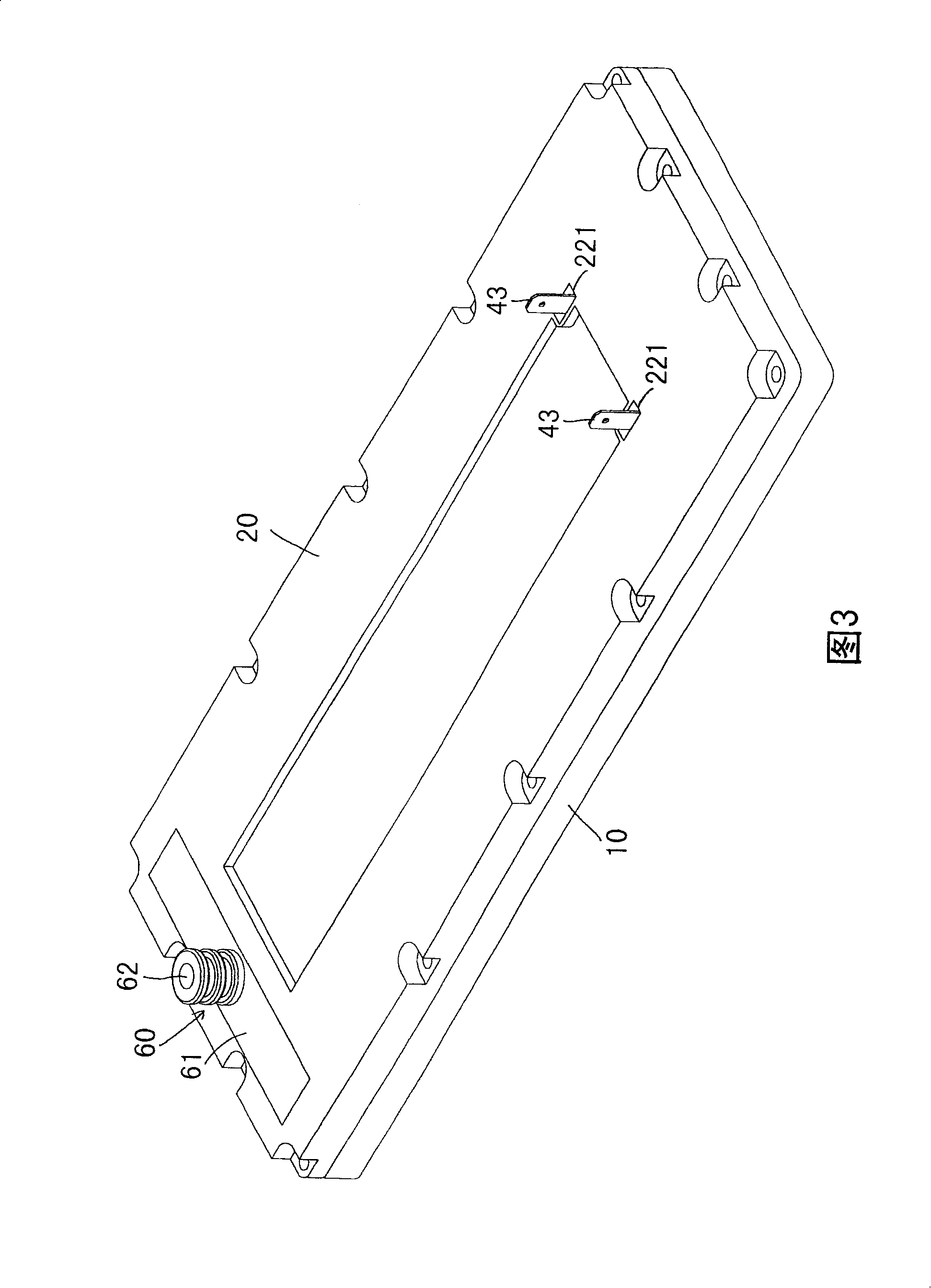
[0149] Embodiment 1, referring to Fig. 3, Fig. 4 shows the three-dimensional combination and the three-dimensional combination sectional view of the first embodiment of the present invention. FIG. 5 is a three-dimensional exploded view of Embodiment 1 of the present invention. And FIG. 6 is a cross-sectional schematic diagram of Embodiment 1 of the present invention. The electrolytic cell is mainly composed of a first housing 10, a second housing 20, two anode electrode plates 30, two cathode electrode plates 40, an acidic water outlet 50, and an alkaline water outlet 60; wherein:

[0150] The inner surface of the first housing 10 is provided with a frame-shaped groove 11, which can be used for setting the water-stop bead Q, and at the same time, it is used for positioning when combined with the second housing 20, and the surrounding can be tightly combined with the second housing 20 by locking components In one piece, a raw water inlet 12 is provided in the middle of the out...

Embodiment 2

[0159] Embodiment 2, please refer to FIG. 10, which shows the three-dimensional combination and the three-dimensional combination cross-sectional view of the second embodiment of the present invention. As shown in FIG. 12 , it is a three-dimensional exploded schematic view of Embodiment 2 of the present invention. And FIG. 13 is a cross-sectional schematic diagram of Embodiment 2 of the present invention. The electrolytic cell is mainly composed of a first shell 10', a second shell 20', an anode electrode plate 30', a cathode electrode plate 40', an acidic water outlet 50', an alkaline water outlet 60', an electrolytic water machine 70' consisting of:

[0160] The inner surface of the first housing 10' is provided with a frame-shaped groove 11', which can be used to set the water-stop bead Q', and at the same time, it is used for positioning when combined with the second housing 20', and the locking components and the second housing can be used around it. The body 20' is clo...


PUM


Abstract

The invention provides a method for slowing electrolyte tank anion and cation membrane laminar flow and a device thereof, wherein, corresponding inner faces of two shells are provided with pole plates on which cathodes and anodes are correspondingly arranged, center positions on shells or pole plates are provided with water intake flow passages by which two electrolytic spaces are divided into, the raw water flows in through water inlets of the water intake flow passages and is electrolyzed directing to both sides, thereby slowing down the water velocity during the electrolytic process of the alkaline water and the acidic water, helping the split flow of the alkaline water and the acidic water and avoiding the mixed flow phenomenon.

Description

technical field [0001] The slow flow method and device for the laminar flow of anion and cation films in an electrolytic cell of the present invention are mainly applied to the slow flow technology of the laminar flow of anion and cation films in an electrolytic water machine. Background technique [0002] see figure 1 Shown: It is a schematic diagram of the shunting state of the invention patent case of Taiwan Patent Publication No. 301644 "Diaphragmless Electrolyzer for Electrolysis of Water". According to the scope of the patent application: [0003] Two anode plates 81 and a cathode plate 82 are mainly arranged in the electrolytic cell 80, and water channels 83 and 84 as electrolysis chambers are formed between the anode plate 81 and the cathode plate 82, and water is passed through the water channels 83 and 84 for simultaneous electrolysis. water to produce acidic water and alkaline water, the anode plate 81 is provided with a slit 85 for the acidic water recovery por...

Claims


Application Information

Patent Timeline
Patent Type & Authority Applications(China)
IPC IPC(8): C25B1/00C25B9/00C02F1/461
Inventor 徐文星
Owner 徐文星
Why Eureka
Try Eureka