High-stability thermostatic controller

A thermostatic controller, high-stability technology, used in temperature control, control/regulation systems, non-electric variable control, etc., can solve the problems of low precision and inconvenient use, and achieve reliable work, cost saving, and stable performance. Effect

Inactive Publication Date: 2008-06-18
JILIN UNIV
View PDF0 Cites 33 Cited by
  • Summary
  • Abstract
  • Description
  • Claims
  • Application Information

AI Technical Summary

Problems solved by technology

This control method is not accurat

Method used


Image

  • High-stability thermostatic controller
  • High-stability thermostatic controller
  • High-stability thermostatic controller

Examples


Embodiment 1

[0038] Embodiment 1 The basic structure and working principle of the high stability constant temperature controller of the present invention

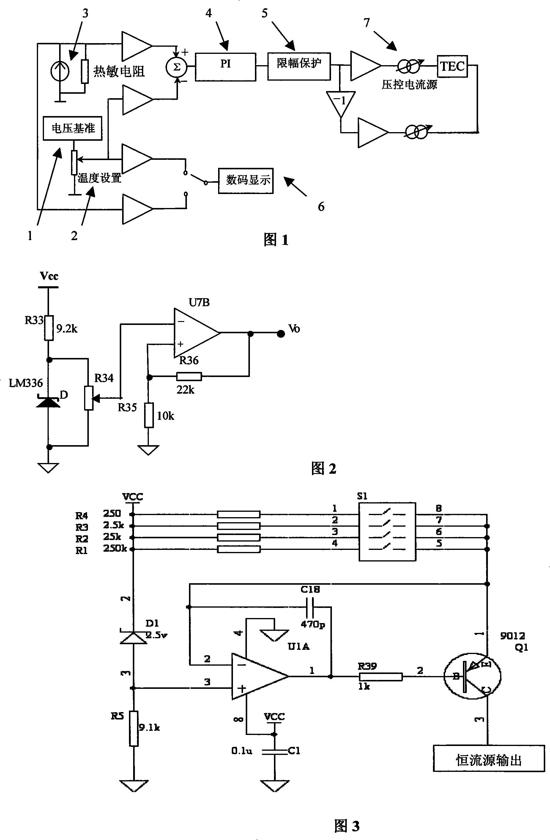
[0039] As shown in Figure 1: the tap output of the potentiometer in the voltage reference circuit (1) is connected to the operational amplifier as a temperature setting circuit (2), and its output is connected to the display circuit (6). The constant current source is connected in series with the temperature sensor, the measuring voltage terminal is connected with the display circuit (6), the temperature setting circuit (2) and the temperature measurement circuit (3) are connected with the subtractor, and the subtractor is connected with the PI control circuit (4), that is, the PI The control modules are connected, and the PI control module is connected with the limiting protection circuit (5). The output of the limiting protection circuit (5) is connected with the TEC driving circuit (7).

[0040] The working principle of the present ...

Embodiment 2

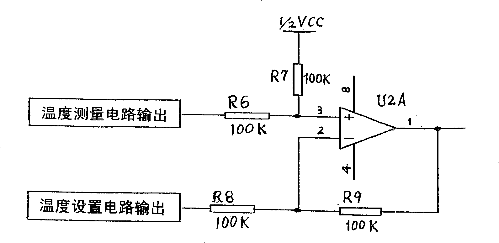
[0046] Embodiment 2 Structure of voltage reference circuit (1) and temperature setting circuit (2)

[0047] As shown in Figure 2, the voltage reference circuit (1) and temperature setting circuit (2) of the present invention include: an external DC power supply (Vcc) is connected to a 9.1k resistor and then connected to a precision voltage reference module (LM336) for grounding; The invented temperature setting circuit (2) is to connect a 10k potentiometer in parallel with the LM336, and its tap is connected to the in-phase input terminal of the operational amplifier U7B; . In addition, in order to improve the driving ability, a voltage follower composed of U2B is added to the output of U7B. The non-inverting input of U2B is connected to the output of U7B, and the inverting input of U2B is connected to its output.

Embodiment 3

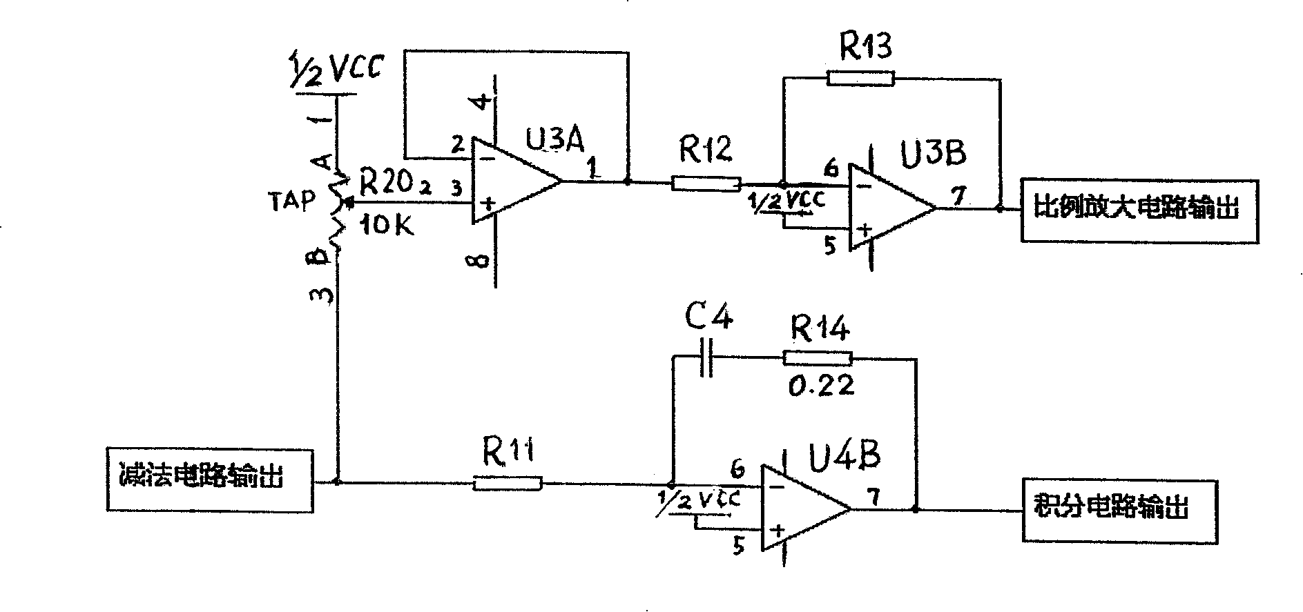
[0048] Embodiment 3 The structure of the temperature measurement circuit (3) of the present invention

[0049] As shown in Figure 3, the temperature measurement circuit (3) of the present invention comprises: external DC power supply (Vcc) connects 2.5V voltage regulator tube D1; The voltage regulator tube D1 anode and the same phase input end of operational amplifier U1A and 9.1k resistance R5 The other end of resistor R5 is connected to ground; the output terminal of operational amplifier U1A is connected to 1k resistor R39 and 470pF capacitor C18; capacitor C18 is connected to the inverting input terminal of operational amplifier U1A, and is connected to four resistors (R1, R2, R3, R4) are connected and connected with the emitter of the triode Q1; the above four resistors (R1, R2, R3, R4) are connected with the external DC power supply (Vcc); the resistor R39 is connected with the base of the triode Q1; the triode The emitter of Q1 is connected with the temperature sensor i...


PUM


Abstract

The invention provides a high-stability and constant-temperature controller and belongs to the technological field of electronic circuit. The invention comprises a voltage reference circuit (1), a temperature setting circuit (2), a temperature measurement circuit (3), a PI control circuit (4), a limiting protection circuit (5), display circuit (6) and a TEC drive Circuit (7); wherein, the TEC drive Circuit (7) comprises a bridge circuit and a voltage negative feedback circuit. The invention has the strong anti-interference capability, the stable performance, and the reliable work; the invention is suitable for the temperature control of high-power laser diodes to make the diodes work for a long time; the temperature control range is 0 DEG C to 80 DEG C; the short-term stability is 0.02 DEG C; the long-term stability is 0.05 DEG C. Besides the use in the constant temperature control of the high-power laser diodes, the invention can be widely used in other fields of modern technology by adjusting the proper control parameters.

Description

technical field [0001] The invention belongs to the technical field of electronic circuits and is suitable for various constant temperature control systems, especially for the temperature control of high-power laser diodes. Background technique [0002] Various types of amplifiers in optical fiber communication systems use laser diodes as light sources. Semiconductor lasers are devices with high power density and extremely high quantum efficiency. Although they are high-efficiency electron-photon conversion devices, due to the inevitable existence of Various non-radiative recombination losses, free carrier absorption and other loss mechanisms make the external differential molecular efficiency only reach 20% to 30%, which means that a considerable part of the injected electric power will be converted into heat, causing the temperature of the laser to rise. The influence of temperature on the laser mainly has the following aspects: [0003] (1) Effect of temperature on thres...

Claims


Application Information

Patent Timeline
IPC IPC(8): G05D23/20
Inventor 田小建单江东汝玉星范文华
Owner JILIN UNIV
Why Eureka
Try Eureka