Fluid dynamic bearing apparatus

A technology of fluid dynamic bearings and bearings, which is applied in the direction of sliding contact bearings, bearings, rotating bearings, etc., and can solve problems such as difficult mass production of high-precision grooves and easy changes in shape

Inactive Publication Date: 2008-06-18
NTN CORP
View PDF1 Cites 9 Cited by
  • Summary
  • Abstract
  • Description
  • Claims
  • Application Information

AI Technical Summary

Problems solved by technology

In the above-mentioned method of forming dynamic pressure grooves by forming roll pressing, the shape of the grooves tends to

Method used


Image

  • Fluid dynamic bearing apparatus
  • Fluid dynamic bearing apparatus
  • Fluid dynamic bearing apparatus

Examples


Embodiment Construction

[0101] Embodiments of the present invention will be described based on the drawings.

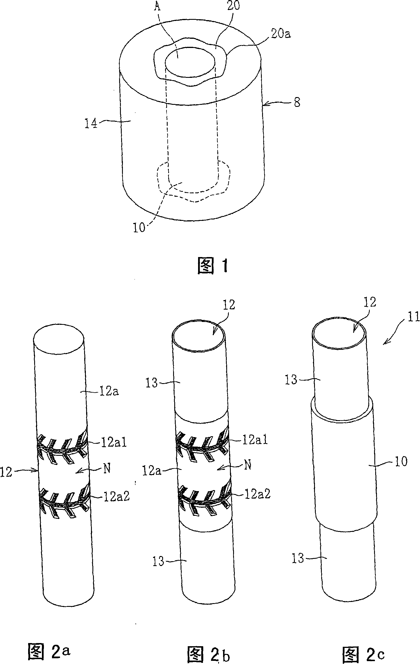
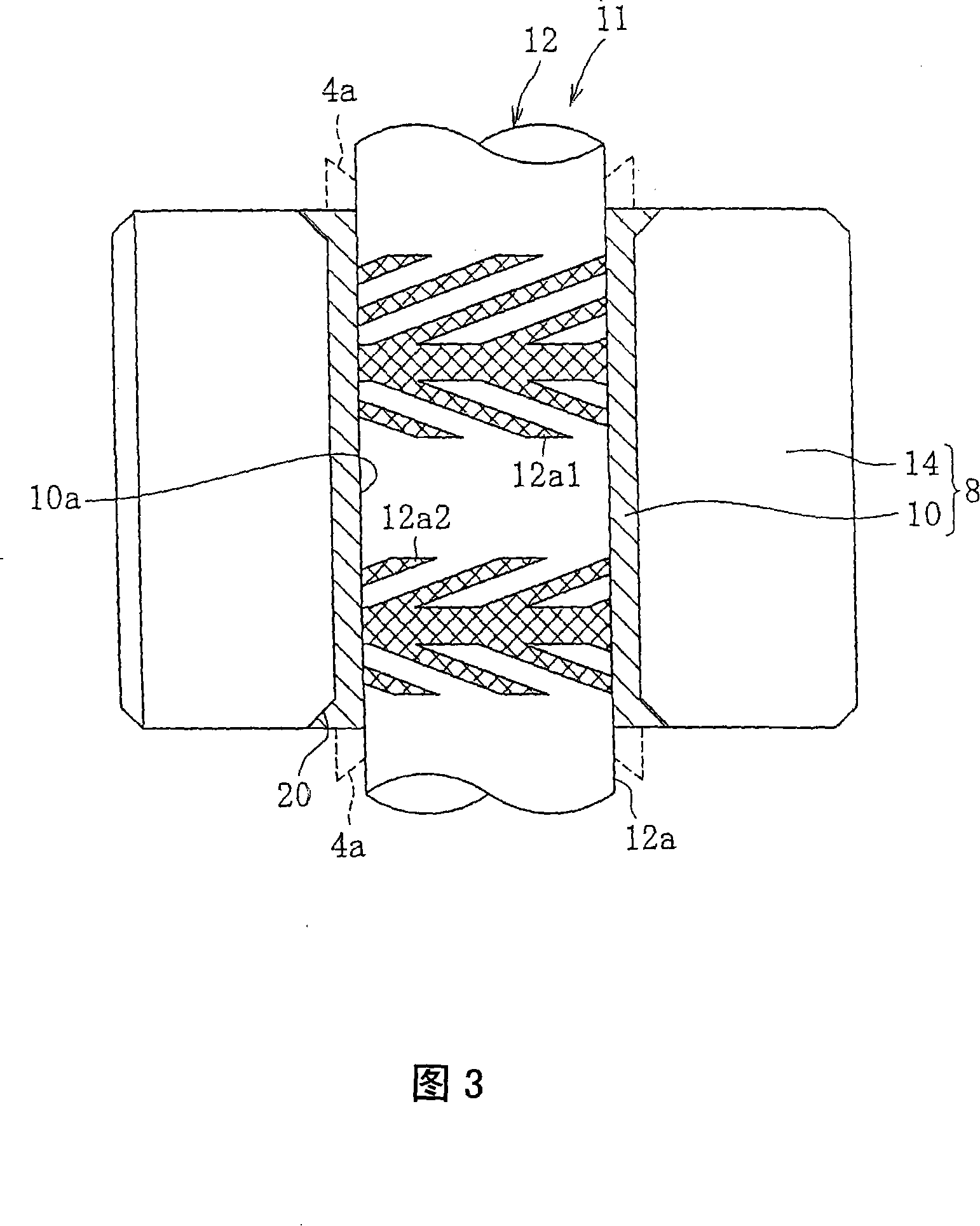
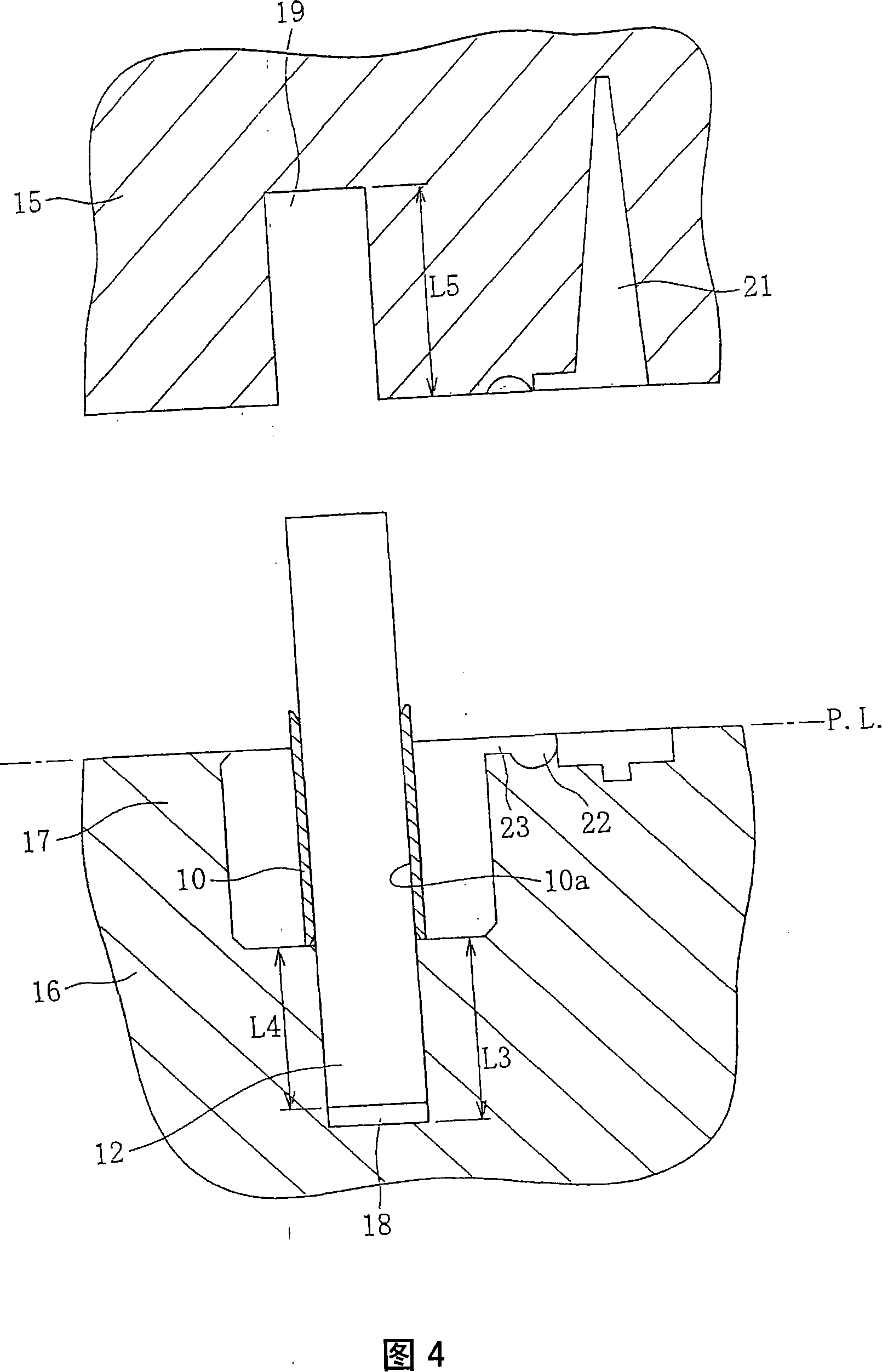
[0102] The bearing member 8 with the construction of the present invention shown in Fig. 1 is manufactured through the following steps: manufacture the main shaft (refer to Fig. 2A); The electroforming process is partially performed to form the electroformed shaft 11 (refer to FIG. 2C); the bearing member 8 is formed by molding the electroformed part 10 of the electroformed shaft 11 with resin or the like (refer to FIG. 5); and the electroformed part 10 and The spindles 12 are separated from each other.

[0103] The main shaft 12 shown in FIG. 2A is formed of a conductive metal material, such as quenched stainless steel. As usual, metal materials other than stainless steel, such as nickel alloys, chrome alloys, and the like, may also be used as long as the plasticity of the electroformed portion 10 is excellent. Even non-metallic materials such as ceramics can be used as the main shaft by ...


PUM


Abstract

The purpose of the invention is a bearing member comprising highly accurate dynamic pressure generating portions and stably manufacturable at low cost. Dynamic pressure grooves (8a1) and (8a2) as the dynamic pressure generating portions are formed in the inner peripheral surface of an electroformed part (10) by electroforming, and the electroformed part (10) is inserted and the bearing member (8) is injection-molded with a resin. A shaft member (2) is inserted to the inner periphery of the bearing member.

Description

technical field [0001] The invention relates to a bearing arrangement for rotatably supporting a shaft member by the action of hydrodynamic pressure generated in a bearing gap. This type of bearing device is called a "fluid dynamic bearing device" and is suitable for use on information devices such as magnetic disk devices such as HDD and FDD, optical disk devices such as CD-ROM / RAM, or such as MD / MO, etc. in a spindle motor in a magneto-optical disk device), in a polygon scanner motor in a laser beam printer (LBP) or the like, or in a small motor in an electronic device such as an axial fan. Background technique [0002] In a fluid dynamic bearing device, the shaft member is usually supported in the radial direction without being in contact with the bearing member by the action of dynamic pressure of fluid generated in the radial bearing gap. In order to generate the dynamic pressure action of the fluid in the radial bearing gap, in a predetermined area of ​​at least any o...

Claims


Application Information

Patent Timeline
IPC IPC(8): F16C33/14F16C17/00
Inventor 森夏比古山下信好大熊真史三谷健一里路文规古森功水谷敏幸
Owner NTN CORP
Why Eureka
Try Eureka