Dip-roll sleeve and method for manufacturing the same

A manufacturing method and technology of sunken rollers, which are applied in the field of manufacturing of sunken roller bushings, can solve the problems of low strength of powder metallurgy bushings, affecting continuous production of galvanizing lines, poor corrosion resistance of molten zinc, etc. The effect of low production cost and thick layer of corrosion resistance of molten zinc

Inactive Publication Date: 2008-06-25
SHENYANG DALU LASER TECH
View PDF0 Cites 30 Cited by
  • Summary
  • Abstract
  • Description
  • Claims
  • Application Information

AI Technical Summary

Problems solved by technology

The shaft sleeve made of this material and manufacturing process has low material utilization rate, poor resistance to molten zinc corrosion, poor wear resistance, and short service life, generally only 10 to 15 days
Another material is a cobalt-based alloy, which is sintered by powder metallurgy. Although the bushing made by this method has improved resistance to molten zinc corrosion, it is difficult to machine and the production cost is high. Low strength, easy to break the shaft sleeve during the production process of galvanized sheet, which seriously affects the continuous production of galvanized line

Method used


Image

  • Dip-roll sleeve and method for manufacturing the same

Examples


Embodiment 1

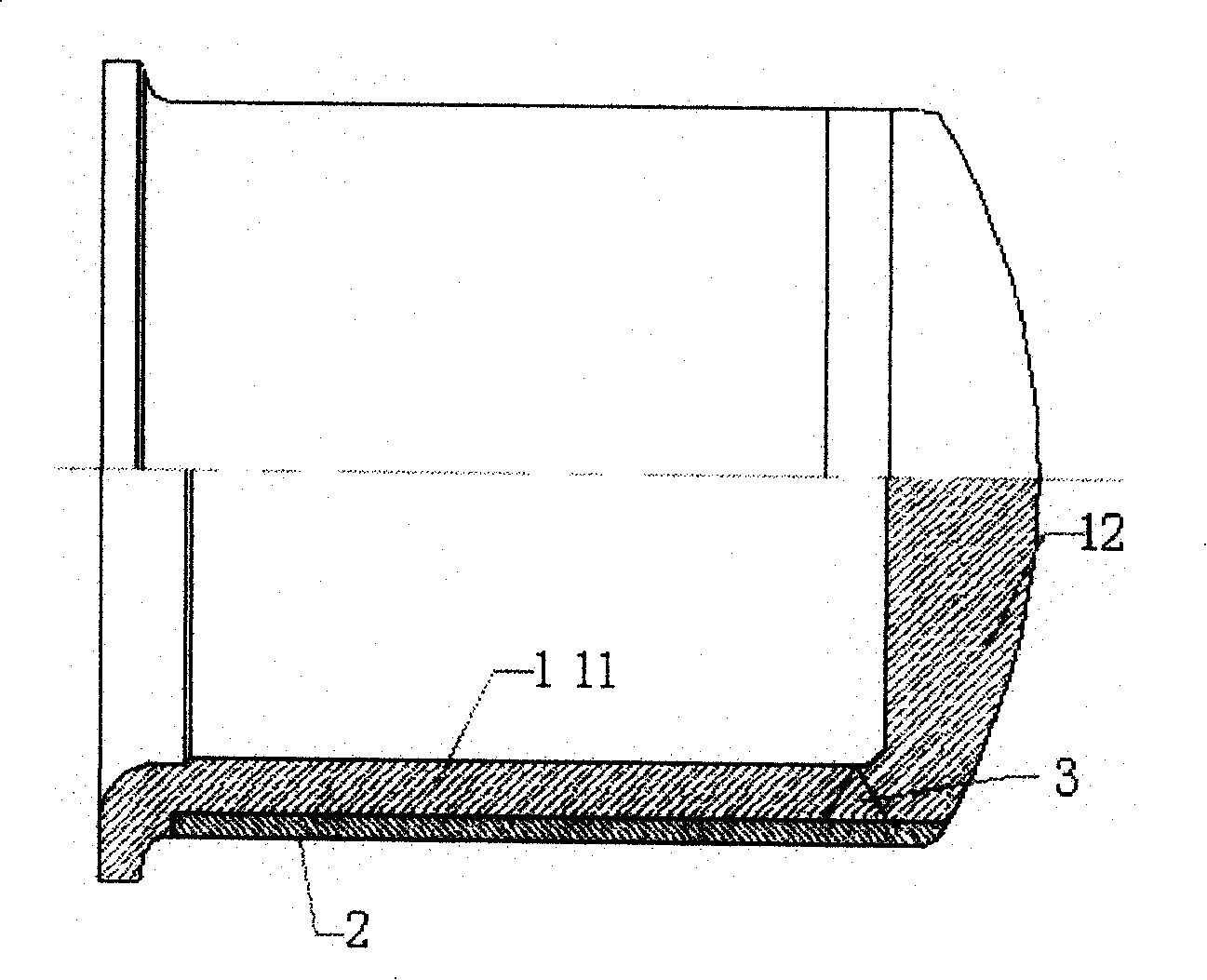
[0015] Shaft structure such as figure 1 As shown: the shaft sleeve is composed of a stainless steel substrate 1 and a cobalt-based laser cladding layer 2. The cobalt-based laser cladding layer 2 covers the stainless steel substrate 1. The stainless steel substrate 1 is welded by an inner sleeve 11 and a plug 12. , 3 is the welding port.

[0016] The process steps are as follows:

[0017] 1. Machining stainless steel inner sleeve 11 with stainless steel pipe and machining plug 12 with stainless steel plate.

[0018] 2. Weld the stainless steel inner sleeve 11 and the plug 12 together.

[0019] 3. Machining, leaving 2~3mm laser cladding allowance.

[0020] 4. Laser cladding, on the outer circle of the stainless steel substrate 1, first use cobalt-based powder with better cladding performance as a primer, and then cladding cobalt-based powder with good wear resistance and molten zinc corrosion resistance to the design size of the shaft sleeve And leave the machine to add a ma...

Embodiment 2

[0023] Shaft structure such as figure 1 As shown: the shaft sleeve is composed of a stainless steel substrate 1 and a cobalt-based laser cladding layer 2. The cobalt-based laser cladding layer 2 covers the stainless steel substrate 1. The stainless steel substrate 1 is welded by an inner sleeve 11 and a plug 12. , 3 is the welding port.

[0024] The process steps are as follows:

[0025] 1. Machining stainless steel inner sleeve 11 with stainless steel pipe and machining plug 12 with stainless steel plate.

[0026] 2. Weld the stainless steel inner sleeve 11 and the plug 12 together.

[0027] 3. Machining, leaving 2~3mm laser cladding allowance.

[0028] 4. Laser cladding, on the outer circle of the stainless steel substrate 1, first use cobalt-based powder with better cladding performance as a primer, and then cladding cobalt-based powder with good wear resistance and molten zinc corrosion resistance to the designed size of the shaft sleeve And leave the machine to add a ...


PUM

PropertyMeasurementUnit
thicknessaaaaaaaaaa

Abstract

The invention provides a sink-roll sleeve, which consists of a stainless steel substrate 1 and a Co-base laser-clad layer 2, with the Co-base laser-clad layer covered on the stainless steel substrate 1. The invention also provides a method for manufacturing the sink-roll, and is characterized in that: the procedures are: 1. processing of the stainless steel substrate 1; 2) mechanical processing; 3) laser cladding, which is cladding a bottom layer first, and then a functional layer on the outer circle of the stainless steel substrate 1, with the parameters for laser cladding including a laser power of between 3000 and 5000 W, a diameter of faculae of between 2 and 5mm, a scan speed of between 2 and 10 mm / s; 4) mechanical processing to the designed dimension. The sink-roll sleeve and the manufacturing method provided by the invention has the advantages of high material utilization rate, molten zinc corrosion resistance layer more than 2 mm millimeter thick, high strength in aspect of the sink-roll sleeve, and of strong adaptability, simple and easy operation, high normative, low production costs and great application value in aspect of the manufacturing method.

Description

technical field [0001] The invention relates to the manufacturing technology of the sinker roller sleeve. Background technique [0002] During the continuous hot-dip galvanizing production of steel strip, the steel strip passes through the sinking roller immersed in the zinc solution to change the direction of movement, that is, it changes from entering the zinc pot for galvanizing to exiting the zinc pot, and the galvanized layer is solidified and cooled. The sinking roller, which rotates with the movement of the strip, is supported on the fixed frame by the sleeves on both sides, and the sleeves act as sliding bearings. [0003] Since the bushing and the sinking roller are in molten zinc, severe molten zinc corrosion usually occurs. At the same time, since the bushing and the bushing are always in a state of relative motion during work, the working life of the bushing is relatively short. short. At present, there are mainly two types of shaft sleeves used in the producti...

Claims


Application Information

Patent Timeline
Patent Type & Authority Applications(China)
IPC IPC(8): C23C2/06C23C24/10
Inventor 刘豫刘玉兰陈常义
Owner SHENYANG DALU LASER TECH
Why Eureka
Try Eureka