Method of preparing multi-component high-frequency thin ferromagnetic film material with component gradient

A ferromagnetic thin film, composition gradient technology, applied in the direction of magnetic layer, magnetic film to substrate application, cathode sputtering application, etc., can solve the problems of increased manufacturing cost, damage to other components, impossible preparation process, etc.

Inactive Publication Date: 2008-06-25
FUJIAN NORMAL UNIV
View PDF0 Cites 18 Cited by
  • Summary
  • Abstract
  • Description
  • Claims
  • Application Information

AI Technical Summary

Problems solved by technology

Heat treatment at such a high temperature not only increases the manufacturing cost, but more importantly, it is incompatible with the traditional Si-based integration process, causing damage to other components, and even making the preparation process impossible.

Method used


Image

  • Method of preparing multi-component high-frequency thin ferromagnetic film material with component gradient
  • Method of preparing multi-component high-frequency thin ferromagnetic film material with component gradient
  • Method of preparing multi-component high-frequency thin ferromagnetic film material with component gradient

Examples


Embodiment 1

[0048] Preparation (Fe) x -(Nd) y o z film material

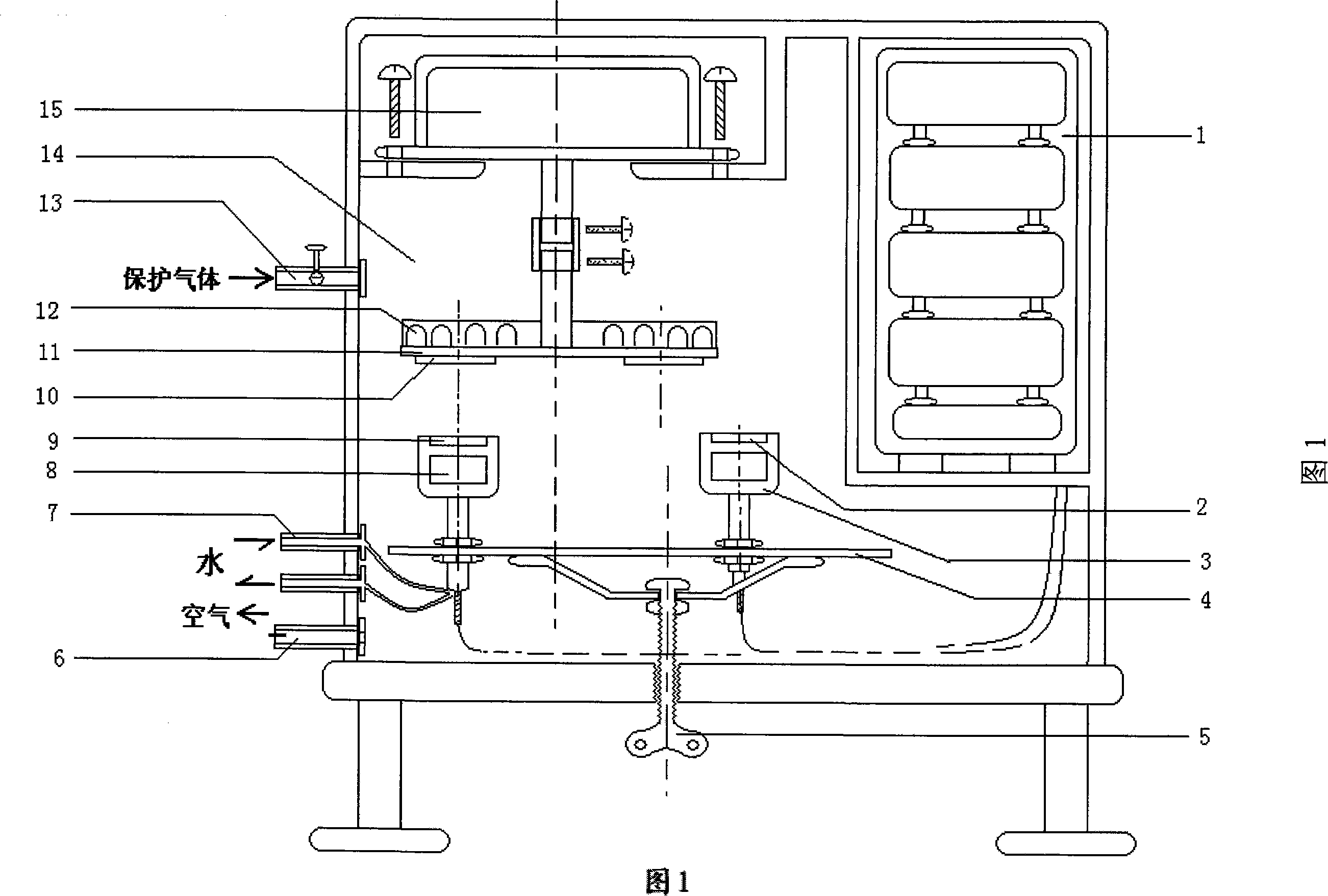
[0049] Three main material targets Fe and one dopant target Nd are respectively placed on the main material target base and the dopant target base according to the positions shown in Figure 1, and the target bases are arranged at a central angle of 90 degrees. The substrates 10 to be sputtered are fixed on the lower bottom surface of the circular rotating sputtering sample plate 11 and arranged correspondingly at a central angle of 90 degrees. Start the vacuum control system, when the background vacuum pressure is lower than 5×10 -6 After Torr, feed high-purity Ar gas and Ar / O=10 / 1 mixed gas two-way gas, the Ar gas flow rate is 50 sccm, the Ar / O mixed gas flow rate is 5 sccm, and the circular rotary sputtering is started when the working pressure of the vacuum chamber is 5.8mTorr Plating the sample disk 11, the rotating speed is set at 40 rpm. The sputtering power of the main material target Fe and the dopant target Nd...

Embodiment 2

[0051] Preparation (Fe) x -(Nd 2 o 3 ) y film material

[0052] With reference to the method described in embodiment 1, with Fe as the main material target, with Nd 2 o 3 is the dopant target. Under background vacuum pressure below 5 x 10 -6 After Torr, feed high-purity Ar gas with a flow rate of 20 sccm, and start the circular rotary sputtering sample disk when the working pressure of the vacuum chamber is 2.8 mTorr, and the rotation speed is set to 30 rpm. Main material target Fe and dopant target Nd 2 o 3 The sputtering power is set to 160 and 170W respectively, and the sputtering time is 160 minutes to obtain (Fe) x -(Nd 2 o 3 ) y System of high-frequency ferromagnetic thin film materials.

Embodiment 3

[0054] Preparation (Co) x -(Nd) y N z film material

[0055] Referring to the method described in Example 1, Co is used as the main material target, and Nd is used as the dopant target. The vacuum pressure in the vacuum chamber is lower than 5×10 -6 After Torr, feed high-purity Ar gas and Ar / N=10 / 1 mixed gas two-way gas, the Ar gas flow rate is 50 sccm, the Ar / N mixed gas flow rate is 10 sccm, and the circular rotary sputtering is started when the working pressure of the vacuum chamber is 6.0mTorrr The plated sample disk was set at 50 rpm. The sputtering power of the main material target Co and the dopant target Nd are respectively set to 80 and 130W, and the sputtering time is 60 minutes, and the (Co) x -(Nd) y N z High-frequency ferromagnetic film material of the system.


PUM


Abstract

The invention relates to a method for preparing a high-frequency ferromagnetic film material with component gradient under the room temperature condition. The invention adopts the proposal that in a vacuum thin film gradient sputtering device, a ferromagnetic material is adopted as a main material target and arranged below a sputtered base plate; simple substances, oxides, nitrides, borides, carbides or phosphides are taken as adulterants to be arranged at the position outwards deviated from the center of the base plate, during the sputtering, the components of the main material target form an even film on the base plate, and the components of an adulterant target form a film provided with the components of the adulterants and distributed in gradient form along a certain direction. The invention adopts the design that the main material target is rightly opposite and the adulterant target is eccentric, the graded distribution of the components of the adulterants is realized, and the purpose that the uniaxial anisotropy is obtained is attained. The saturation magnetization (Ms) of the prepared film material is 8 to 25 kG, the equivalent field (Hk) of the uniaxial anisotropy, etc. is 50 to 400 Oe or higher, and the self-resonant frequency is close to 3G Hz or higher.

Description

technical field [0001] The invention relates to a method for preparing a high-frequency ferromagnetic thin film material, in particular to a multi-component high-frequency ferromagnetic thin film material with high uniaxial anisotropy and composition gradient without heat treatment at room temperature Preparation. technical background [0002] As the communication market gradually matures and develops, related IC applications continue to grow, and more and more manufacturers have increased the application ratio of system-on-chip (SOC). In real product manufacturing, not all components are suitable for integrated process. Among them, the inductance element occupies a relatively large area, and it has not been possible to design it into an integrated circuit in the past. In recent years, the application of high-frequency ferromagnetic thin film materials has made it possible for inductive components to participate in integration. At present, the integration technology of hi...

Claims


Application Information

Patent Timeline
Patent Type & Authority Applications(China)
IPC IPC(8): H01F10/14H01F41/18
Inventor 李山东杜正恭刘美梅王大伟李培友程唤龄
Owner FUJIAN NORMAL UNIV
Why Eureka
Try Eureka