
Spiral fluorescent tube and manufacturing method therefor

A technology of fluorescent lamp tube and manufacturing method, which is applied in the direction of tube/lamp screen manufacturing, application of luminous paint, etc., can solve the problems of difficult flow of powder slurry, low powder coating efficiency, waste of fluorescent powder, etc.

Inactive Publication Date: 2008-06-25
FUJIAN YDJ LIGHT
View PDF0 Cites 6 Cited by
  • Summary
  • Abstract
  • Description
  • Claims
  • Application Information

AI Technical Summary

Problems solved by technology

[0003] The amount of slurry injected into the spiral fluorescent tube by these two existing manufacturing methods is much larger than the amount of slurry actually required to coat the inner surface of the lamp tube. The powder slurry has a certain viscosity, the inner channel of the spiral fluorescent tube is curved, and the helix angle is small. The excess powder slurry is not easy to flow out in the spiral fluorescent tube, resulting in uneven thickness of the fluorescent powder coating on the inner surface of the tube. Assuming that it is perpendicular to the spiral On the cross-section inner wall of the fluorescent lamp tube, the thickness of the slurry on the upper inner wall is n, and the thickness of the slurry on the lower inner wall is m. In general, n<m
Moreover, the thickness of the phosphor paste is very thick, which not only wastes the phosphor, but also increases the power consumption during drying, and reduces the powder coating efficiency of the spiral fluorescent lamp tube.
Not only the powder coating efficiency is low, but also the traces of phosphor powder flow will block light, reducing the light efficiency of the lamp tube

Method used


Image

  • Spiral fluorescent tube and manufacturing method therefor
  • Spiral fluorescent tube and manufacturing method therefor
  • Spiral fluorescent tube and manufacturing method therefor

Examples


Embodiment Construction

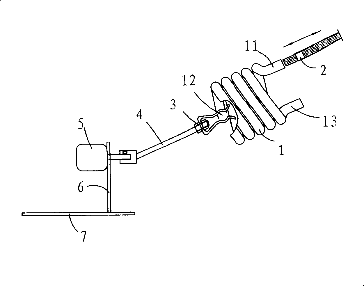
[0020] Such as Figure 3a , 3b , 3c, 3d, 3e, and 3f, a powder coating device for the inner wall of a full double-helix fluorescent lamp (patent applied for), including a spiral fluorescent lamp bright tube 1, a powder injection slurry conduit 2, and a spiral fluorescent lamp bright tube 1 A port 11 is aligned with the powder injection slurry conduit 2, and also includes an exposed pipe fixture 3, a rotary shaft 4, a motor 5, and a bracket 6; the exposed pipe fixture 3 clamps the spiral fluorescent lamp open pipe 1; one end of the rotary shaft 4 is installed with an exposed pipe fixture 3 , the other end is connected to the motor 5; the 4 axis of the rotary shaft coincides with the 1 axis of the spiral fluorescent lamp bright tube; the motor 5 is installed on the bracket 6, and multiple sets of the above-mentioned powder coating devices are installed on the rotary table 7 to become a powder coating machine that can rotate continuously . The electric motor 5 is a motor that ca...


PUM


Abstract

The invention relates to a spiral fluorescent lamp tube and the manufacturing method thereof. The processing steps of the method mainly comprises the steps that the axial line of the exposed tube of the spiral fluorescent lamp is positioned upward to form a certain angle with the level line, the port of the lamp tube is positioned upward, and the top part of the luminous tube is positioned downward; by rotating the exposed tube of the spiral fluorescent lamp forward and backward, powder slurry poured in the exposed tube of the spiral fluorescent lamp flows and is coated on the inner wall of the exposed tube of the spiral fluorescent lamp evenly, and then the spiral fluorescent lamp tube is continued to be rotated, the inner part of the lamp tube is blown, heated and dried, until the spiral fluorescent lamp tube is formed; therefore the thickness of the fluorescent powder coating layer on the inner surface of the spiral fluorescent lamp tube is even, a great amount of fluorescent powder can be saved, the luminescent effect of the fluorescent lamp tube is enhanced, the current drain during the drying is reduced, and the efficiency of powder coating of the lamp tube is greatly enhanced.

Description

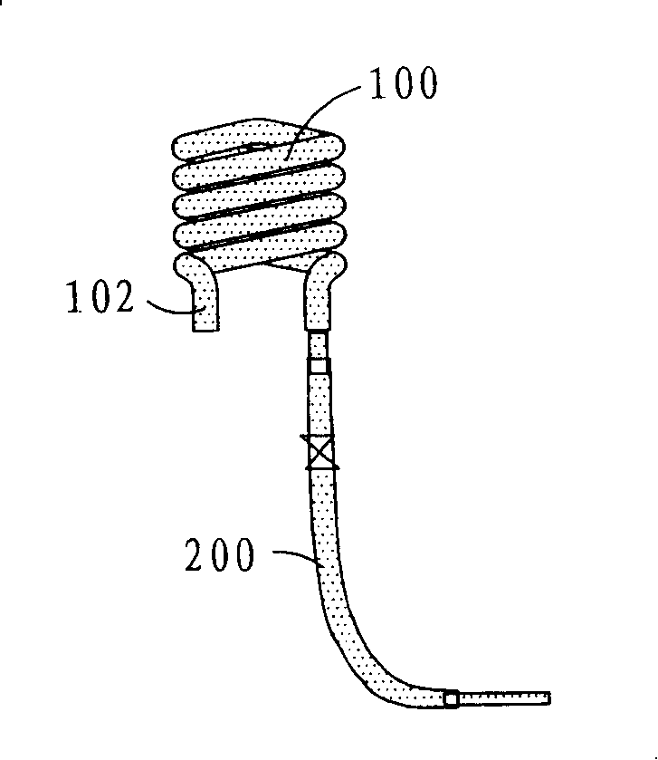
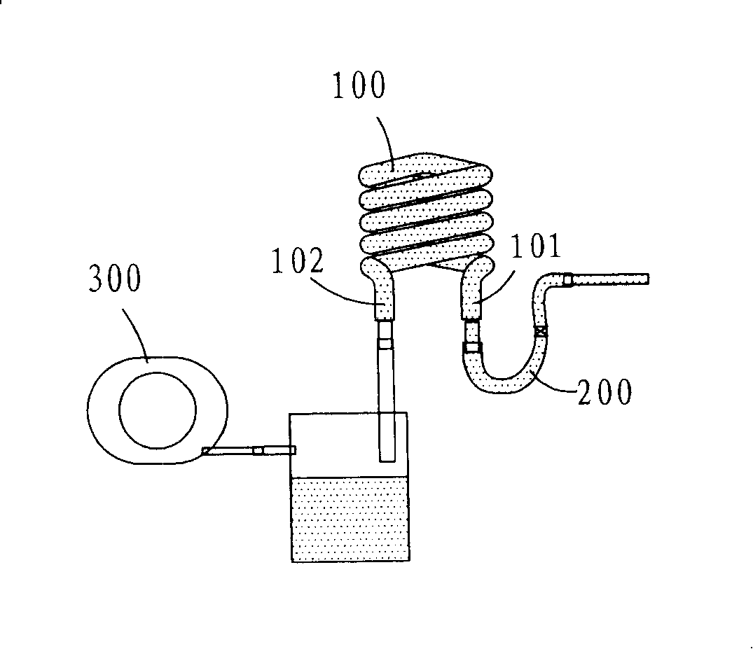
【Technical field】 [0001] The invention relates to a fluorescent lamp tube and a manufacturing method thereof, in particular to a spiral fluorescent lamp tube and a manufacturing method thereof. 【Background technique】 [0002] At present, the manufacturing method of the spiral fluorescent tube is: as figure 1 As shown, one manufacturing method is to place the spiral fluorescent lamp bright tube 100 vertically, and the spiral fluorescent lamp bright tube 100 has a port 101 facing down corresponding to the powder injection slurry conduit 200, and the powder slurry 201 is passed through the powder injection slurry conduit by a certain air pressure 200 is injected from one port 101 of the spiral fluorescent lamp 100, and the other port 102 flows out; as figure 2 As shown, there is also a manufacturing method in which one port 101 of the spiral fluorescent lamp bright tube 100 is connected to the powder injection slurry conduit 200, and the other port 102 is connected to the mou...

Claims


Application Information

Patent Timeline
IPC IPC(8): H01J9/22
Inventor 赖勇清
Owner FUJIAN YDJ LIGHT
Learn More