Vacuum metal smelting heat accumulation reducing furnace system

A metal smelting and reduction furnace technology, applied in the field of vacuum metal smelting regenerative reduction furnace system, can solve the problems of limited production capacity, slow temperature rise, low thermal conductivity, etc., and achieve low smoke pollution, complete combustion, and high heat utilization rate high effect

Inactive Publication Date: 2011-03-23
GUIZHOU SHIJI TIANYUAN MINING IND
View PDF0 Cites 0 Cited by
  • Summary
  • Abstract
  • Description
  • Claims
  • Application Information

AI Technical Summary

Problems solved by technology

The existing reduction tank has a tubular hollow structure, which is placed in the reduction furnace to heat the reduced material. The heat is transferred from the outside of the reduction tank to the material. The thermal conductivity is low and the temperature rises slowly. It takes a long time to reach the reaction temperature. The time required until the reduction reaction is basically completed is generally between 8 and 12 hours, and the production capacity is limited

Method used


Image

  • Vacuum metal smelting heat accumulation reducing furnace system
  • Vacuum metal smelting heat accumulation reducing furnace system

Examples


Embodiment Construction

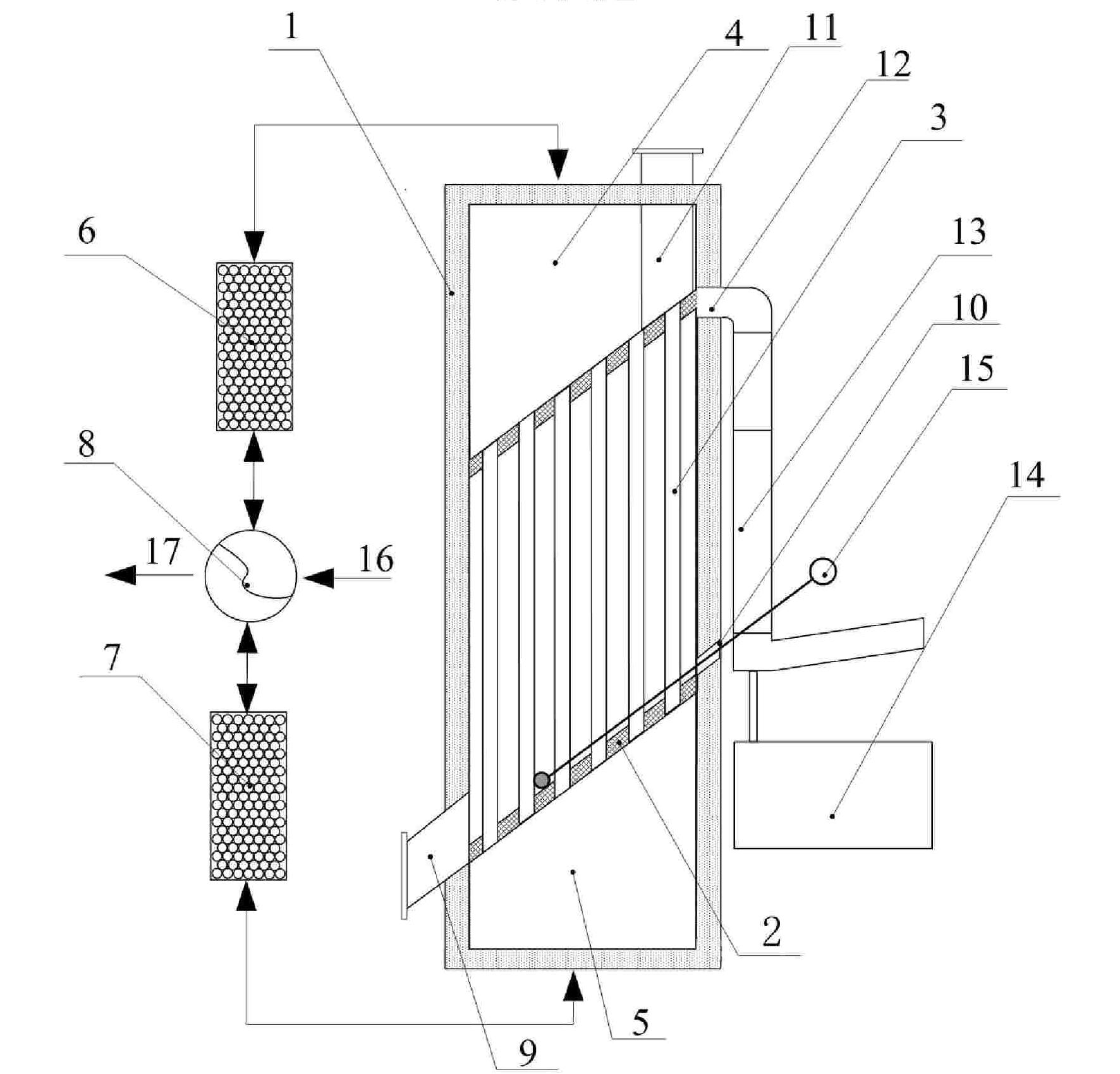
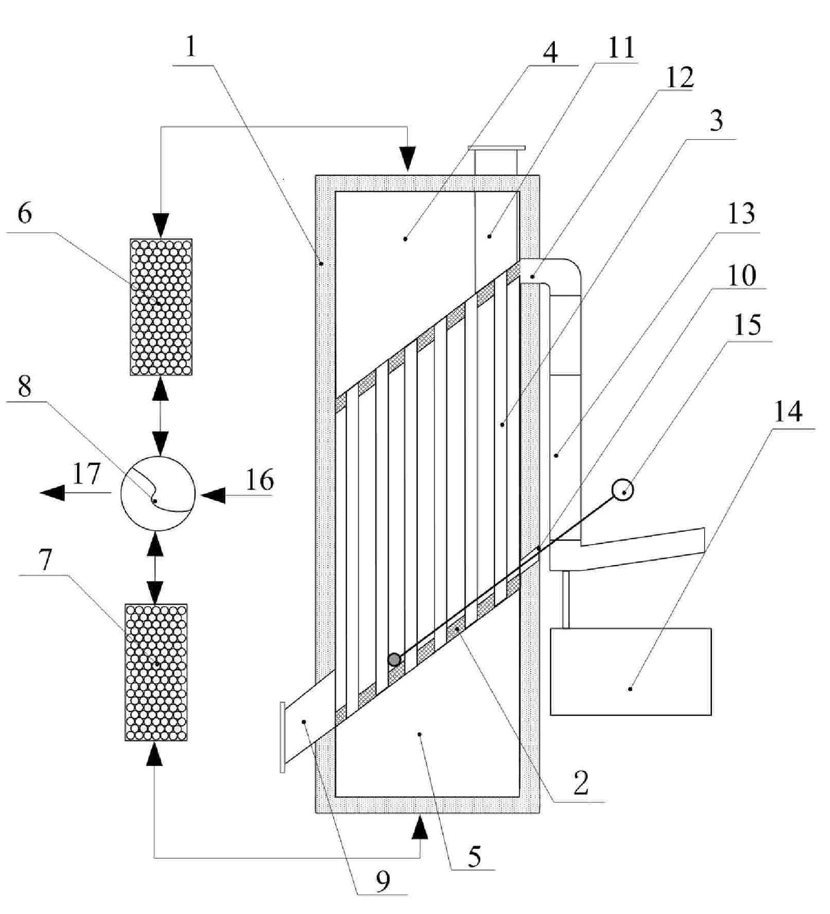
[0016] Example. A vacuum metal smelting regenerative reduction furnace system, such as figure 1 As shown, it includes a reduction furnace 1, a reduction kettle 2, a regenerative combustion system and a liquid metal collection system. The reduction kettle is provided with a group of radiant tubes 3 arranged in an array and running through the reduction kettle. The radiant tubes can be arranged parallel to the front and rear side walls of the reduction kettle, or can be arranged horizontally. When the radiant tubes are arranged in parallel with the front and back side walls of the reduction kettle, the reduction kettle is arranged in the middle of the reduction furnace so that the upper combustion chamber 4 and the lower combustion chamber 5 are formed in the reduction furnace; The furnace forms a left combustion chamber 4 and a right combustion chamber 5; the two combustion chambers are penetrated by a radiant tube, so that the hot flue gas in the combustion chamber can pass t...


PUM


Abstract

The invention discloses a vacuum regenerative and reduction furnace system for metal smelting, which comprises a reduction furnace (1), a reduction kettle (2), a regenerative burning system and a liquid-state metal collection system. The reduction kettle with a bevel bottom structure is provided with a radiation pipe (3) penetrating in the reduction kettle and is arranged at the middle section ofthe reduction furnace to divide the reduction furnace into an upper or a left combustion chamber (4) and a lower or a right combustion chamber (5), and the two combustion chambers are communicated with each other through the radiation pipe (3), so that the hot smoke in the combustion chambers can pass through the radiation pipe (3). The two combustion chambers are respectively connected with eachother a regenerative combustion system, which is used for storing the heat of smoke discharged from the reduction furnace after heating materials through the radiation pipe and for controlling the alternate combustion of the combustion chambers and the flow direction of the high-temperature gas in the radiation pipe. A reduction material in the reduction kettle produces a metal vapor after reduction reaction, and the metal vapor is collected by the liquid-state metal collection system and is directly cast or conveyed to a refining furnace. The invention has the advantages of high heat utilization rate, good power saving effect, complete combustion and short reduction reaction time.

Description

technical field [0001] The invention relates to a reduction furnace, in particular to a vacuum metal smelting regenerative reduction furnace system. Background technique [0002] In the production of metal vacuum smelting, the reduction material produced by the batching pressing process is sent to the reduction tank for reduction reaction. Generally, the reduction reaction temperature is required to be higher than 1100 ℃, and the pressure is less than 10Pa ~ 13Pa. The reduction reaction is realized by heating the reduction tank in the reduction furnace with the fuel or heating the radiant tube of the reduction tank to make the reduction material reach the required temperature value. The existing reduction tank is a tubular hollow structure, which is placed in the reduction furnace to heat the reduction material, and the heat is transferred from the outside of the reduction tank to the material. The time required until the reduction reaction is basically completed is general...

Claims


Application Information

Patent Timeline
Patent Type & Authority Patents(China)
IPC IPC(8): C22B5/16
Inventor 张继强黄贵明
Owner GUIZHOU SHIJI TIANYUAN MINING IND
Why Eureka
Try Eureka