Refraction-diffraction mixed telescope optical system

An optical system and a refracting-diffractive hybrid technology, which is applied in the field of refracting-diffractive hybrid telescope optical systems, can solve the problems of processing and inspection difficulties of sub-reflectors, and achieve the effects of reducing assembly difficulty, manufacturing cost, and manufacturing cost.

Inactive Publication Date: 2008-07-02
SHANGHAI INST OF TECHNICAL PHYSICS - CHINESE ACAD OF SCI
View PDF0 Cites 14 Cited by
  • Summary
  • Abstract
  • Description
  • Claims
  • Application Information

AI Technical Summary

Problems solved by technology

[0008] The object of the present invention is to provide a kind of refraction-diffraction mixed Cassegrain type telescope optical system, its main reflector and sub-reflecto

Method used


Image

  • Refraction-diffraction mixed telescope optical system

Examples


Embodiment Construction

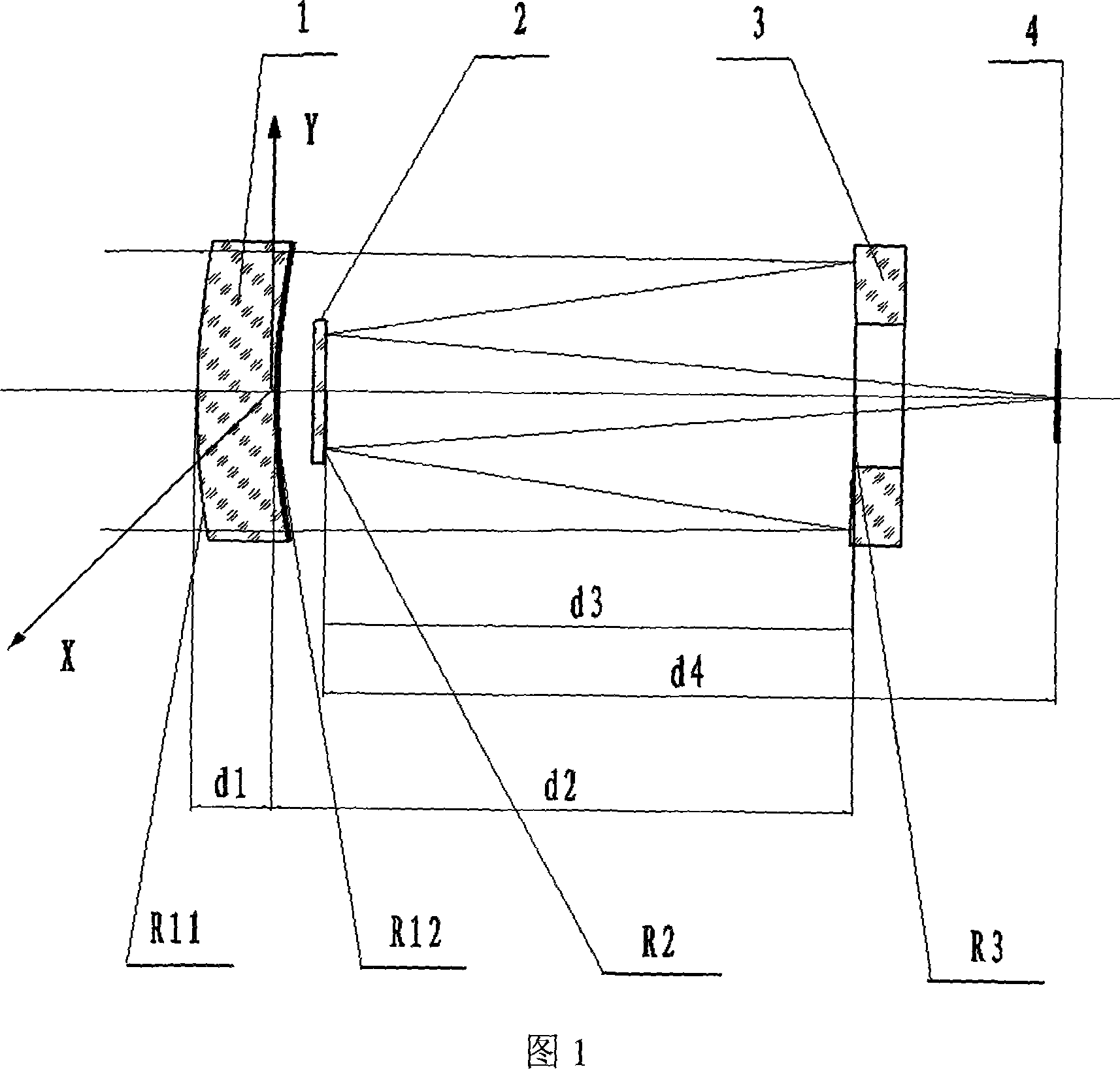
[0025] According to the optical structure of attached drawing 1, we designed the optical system of a fold-diffraction hybrid telescope. The correction mirror 1 is made of quartz glass material. The field of view of the optical system is equivalent to that of the Ridge-Krekion telescope, and the optical design result is close to the imaging quality of the system Diffraction limit. The specific technical indicators of the optical system are as follows:

[0026] Telescope aperture: φ125mm;

[0027] Relative aperture D / F: 1 / 8;

[0028] System focal length: 1000mm;

[0029] Working wavelength: 0.4861μm~0.6563μm;

[0030] Full field of view: 20';

[0031] The specific structural design parameters of the optical system are shown in Table 1.

[0032] Table 1

[0033]


PUM


Abstract

The invention discloses an optical system for a refractive/diffractive telescope, mainly applying in the astronomical observation, imaging of objectives at long distance, etc. The optical system comprises a corrective lens, a primary reflector and a sub-reflector in the sequence from object space to image space. The corrective lens of optical element in front of the system is a binary diffractive lens of optical element. Light beam from the object space passes through the corrective lens of the binary diffractive element, and irradiates on the primary reflector, and then is reflected to the sub-reflector by the primary reflector, finally finishes imaging after being reflected to the imaging plane by the sub-reflector and. Both the primary and the sub-reflector of the optical system adopt spherical reflectors. The processing, inspection and assembly of the reflectors become much easier, obviously reducing the manufacturing cost and improving the processing efficiency. The binary diffractive corrective lens can be produced in batch through the molding of optical plastics, which can further reduce the manufacturing cost.

Description

technical field [0001] The invention relates to binary optics, optical elements, and optical system design, and specifically refers to a refraction-diffraction hybrid telescope optical system, which is mainly used in astronomical observation, remote object imaging and other occasions. Background technique [0002] Astronomical telescopes and various long-focus telescopic objectives widely use an optical system with two reflector structures. This optical system structure was invented by Cassegrain in 1672. The large reflector is called the main reflector, and the small one is called the main reflector. The secondary reflector, usually with a hole in the center of the primary reflector, forms an image behind the primary reflector. Mr. Su Dingqiang made a detailed analysis and introduction of the structural characteristics of this classic Cassegrain telescope system (see http: / / samuel.lamost.org / basic / dict / baike / twdbk27988.html). The primary and secondary reflectors of the Cas...

Claims


Application Information

Patent Timeline
IPC IPC(8): G02B17/08
Inventor 沈蓓军
Owner SHANGHAI INST OF TECHNICAL PHYSICS - CHINESE ACAD OF SCI
Why Eureka
Try Eureka