Hemming machine for sewing trousers bottom

A technology of reel machine and trouser leg, applied to sewing machine components, sewing machine control devices, sewing equipment, etc., can solve the problems of complex structure, frequent mechanical failure, difficult cloth, needle synchronization, etc., achieve reasonable force transmission structure, reduce Damage rate, effect of avoiding needle dragging

Inactive Publication Date: 2011-05-18
殷贵怀
View PDF0 Cites 0 Cited by
  • Summary
  • Abstract
  • Description
  • Claims
  • Application Information

AI Technical Summary

Problems solved by technology

[0002] Existing industrial sewing machines for trouser legs include integral machine head, platen, tripod, wire rack, wire transmission parts and motor. The structure of the tugboat is complicated, not only the mechanical failure occurs frequently, but also it is difficult to synchronize the cloth and the needle when the cloth is running, and the phenomenon of needle dragging and broken needles often occurs. phenomenon, but still failed to fundamentally solve the phenomenon of needle dragging and broken needles
In addition, when it is necessary to adjust the needle pitch of the processed cloth, it is necessary to replace the required needle pitch gear and adjust the pendulum frame to adjust the needle pitch, which reduces the work efficiency and shortens the service life of the machine
In the prior art, there is no oil pump in the lubricating oil path of the roller foot machine, and the oil is only dipped into the oil cup through the belt, which cannot supply enough oil when the machine is running at high speed, which will cause the machine to fail due to lack of oil when running at high speed The machine is damaged, and the oil circuit of the currently used roller foot machine cannot reach the shuttle bed, and it is manually lubricated. If there is negligence, the shuttle bed will be damaged in a short time, and the machine has to be replaced with a new shuttle bed to make the machine work normally.
In the prior art, the presser foot structure of the roller foot machine is heavy, the operator must use both feet to work to make the machine run, and the hook structure is complicated

Method used


Image

  • Hemming machine for sewing trousers bottom
  • Hemming machine for sewing trousers bottom
  • Hemming machine for sewing trousers bottom

Examples


Embodiment Construction

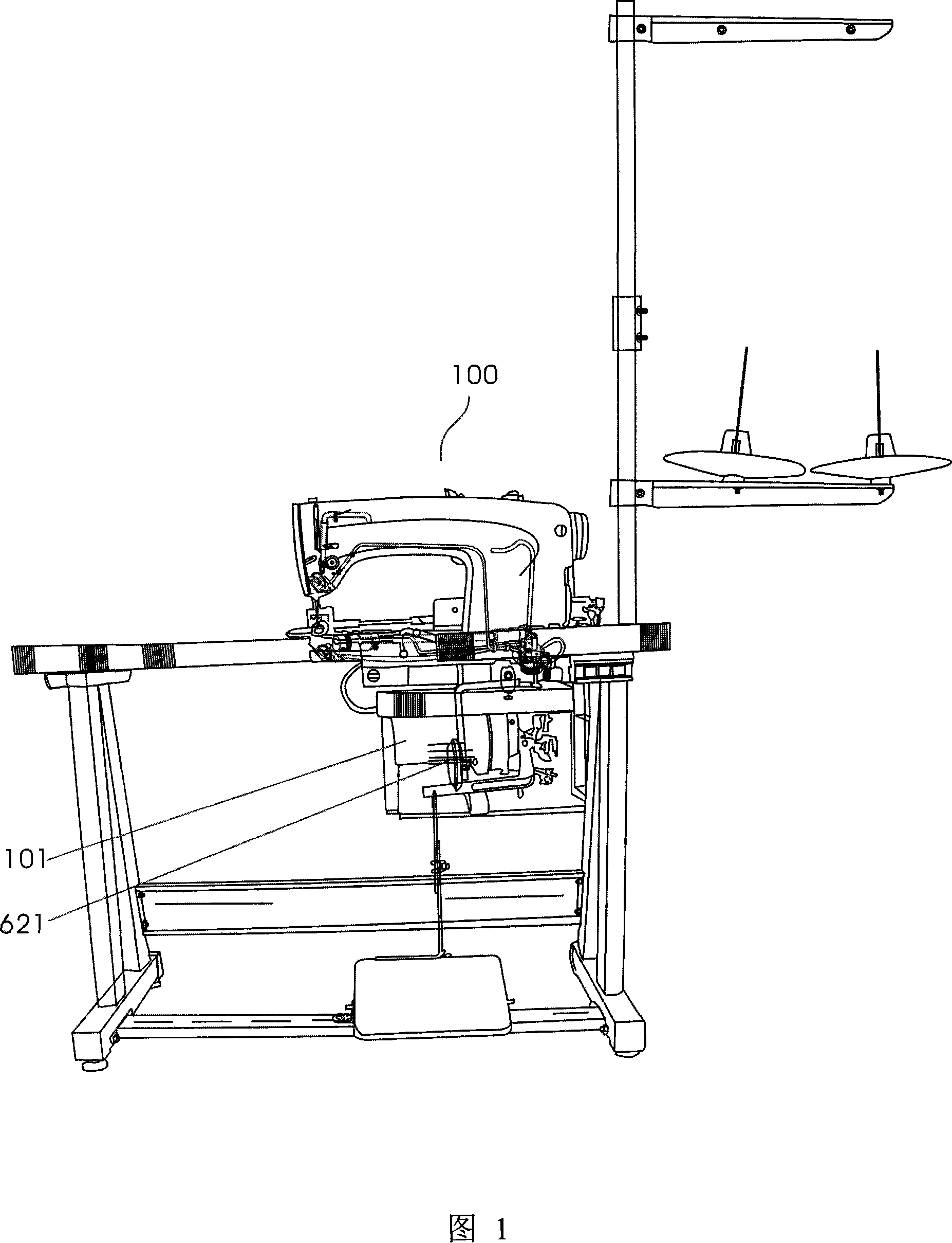
[0020] Fig. 1 is a schematic view of the front appearance of a wheel machine for sewing trouser legs according to the present invention. The present invention is an improvement to the existing roller foot machine, which improves the partial structure inside the integral machine head 100 and adds a lubricating oil supply pipeline. The knee block pad 621 in the knee control mechanism is located at the position where the operator's knee is convenient to touch.

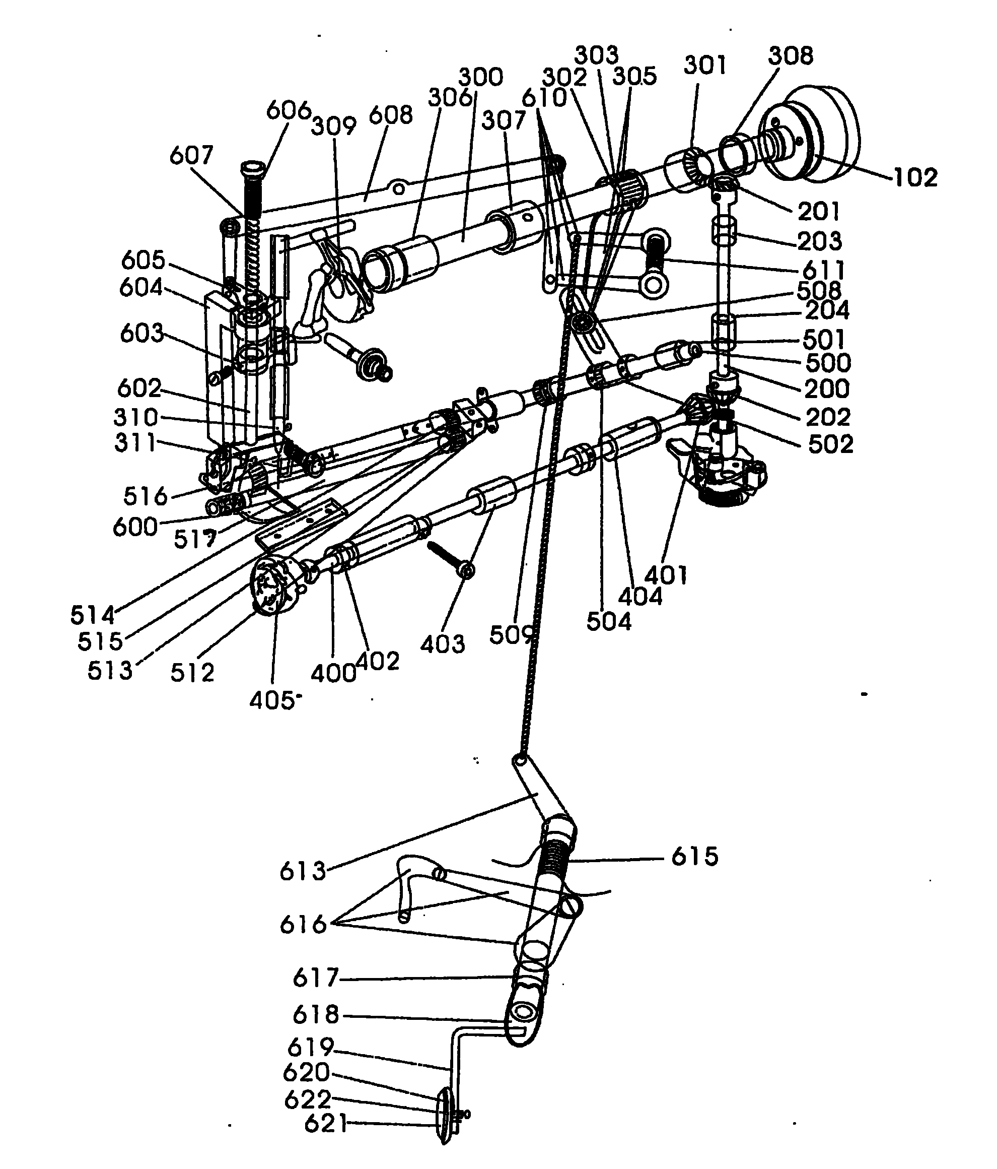
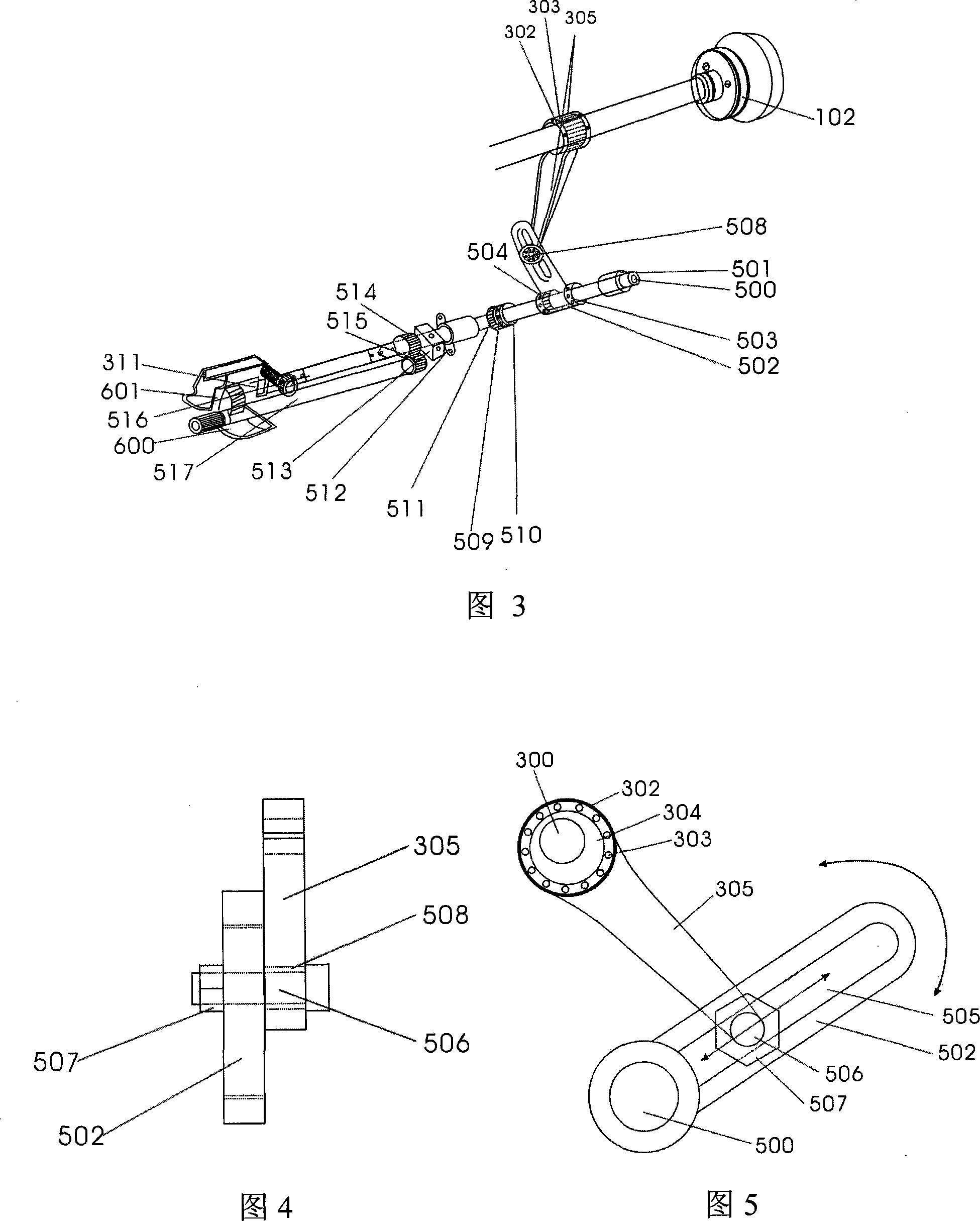
[0021] Such as figure 2 As shown, the cloth feeding tugwheel assembly of the integral head 100 of the roller foot machine is vertically provided with a vertical shaft assembly, and the two ends of the vertical shaft 200 are respectively provided with an upper vertical shaft bevel gear 201 and a vertical shaft lower bevel gear 202 . An upper shaft assembly and a lower shaft assembly are arranged in the horizontal direction. The upper shaft gear 301 of the upper shaft assembly meshes with the vertical shaft upper bevel gea...


PUM


Abstract

The invention provides a special streamlined lockstitch for sewing cuff, wherein a cloth feed tugboat assembly of an integral machine head comprises a vertical shaft component which is vertically arranged and whose both ends are provided with angular wheels, an upper shaft component and a lower shaft component which are horizontally arranged and are respectively geared with the angular wheels. The upper shaft component is connected with a synchronous shaft component through a coupling device, the synchronous shaft component is arranged between the upper shaft component and the lower shaft component, the synchronous cloth feed is achieved through a synchronous shaft, and needle hauling and needle cutting are avoided. The coupling component comprises an eccentric strap, a connecting bar component and a needle distance adjuster, the eccentric strap is a cam structure, both ends of the connecting bar component are respectively and fixedly connected with the eccentric strap and a needle distance adjusting screw rod in a chute of the needle distance adjuster, the spacing of needle distance can be adjusted through changing the position of a screw, and a gear wheel is not needed to be changed, the operation is simple. A lever component and a restoring spring component are arranged in a knee control-foot pressing component, the force transferring structure in operation is more reasonable and labor-saving. An oil pump is arranged in an oil way, which can meet the requirements of the lubrication of an integral machine, and can lower the damage ratio of components in the machine.

Description

technical field [0001] The invention relates to industrial sewing machine technology, in particular to a roller foot machine for sewing trouser legs. Background technique [0002] Existing industrial sewing machines for trouser legs include integral machine head, platen, tripod, wire rack, wire transmission parts and motor. The structure of the tugboat is complicated, not only the mechanical failure occurs frequently, but also it is difficult to synchronize the cloth and the needle when the cloth is running, and the phenomenon of needle dragging and broken needles often occurs. phenomenon, but still failed to fundamentally solve the phenomenon of needle dragging and broken needles. In addition, when the needle pitch of the processed cloth needs to be adjusted, the required needle pitch density gear must be replaced and the pendulum needle frame adjusted to adjust the needle pitch density, which reduces the work efficiency and shortens the service life of the machine. In th...

Claims


Application Information

Patent Timeline
Patent Type & Authority Patents(China)
IPC IPC(8): D05B1/00D05B27/10D05B27/22D05B29/06D05B29/12D05B69/00D05B71/00
Inventor 殷贵怀
Owner 殷贵怀
Why Eureka
Try Eureka