Unlock instant, AI-driven research and patent intelligence for your innovation.

Car engine electronic air throttle control system and its control method

A technology of electronic throttle and automobile engine, which is applied in the direction of engine control, electrical control, machine/engine, etc. It can solve the problems of complicated force on the throttle valve, increased control difficulty, and prolonged time, and achieves improved transient response, The effect of high reliability and simplified design

Inactive Publication Date: 2008-07-09
CATARC AUTOMOTIVE TEST CENT TIANJIN CO LTD +1
View PDF2 Cites 16 Cited by
  • Summary
  • Abstract
  • Description
  • Claims
  • Application Information

AI Technical Summary

Problems solved by technology

[0008] To sum up, the common technical problem of automobile throttle control system in the prior art is that the same control method is adopted for the forward and reverse output control of the throttle body, due to the effect of the return spring in the throttle valve and the friction and other factors complicate the force of the throttle valve and increase the difficulty of control. When the throttle valve rotates in different directions, the tension generated by the main nonlinear spring is different, and the rotation range is also different, resulting in positive and negative rotation. The models are different, and the same control method is used in the forward and reverse directions, which will inevitably lead to the control in one direction, although the opening of the throttle valve can be controlled in time to the desired opening, but the control in the other direction can also control the opening of the throttle valve. If the opening degree is controlled at the desired opening degree, the time used will be extended, resulting in slow response

Method used


Image

  • Car engine electronic air throttle control system and its control method
  • Car engine electronic air throttle control system and its control method
  • Car engine electronic air throttle control system and its control method

Examples


Embodiment Construction

[0039] The present invention will be described in further detail below in conjunction with the accompanying drawings and specific embodiments.

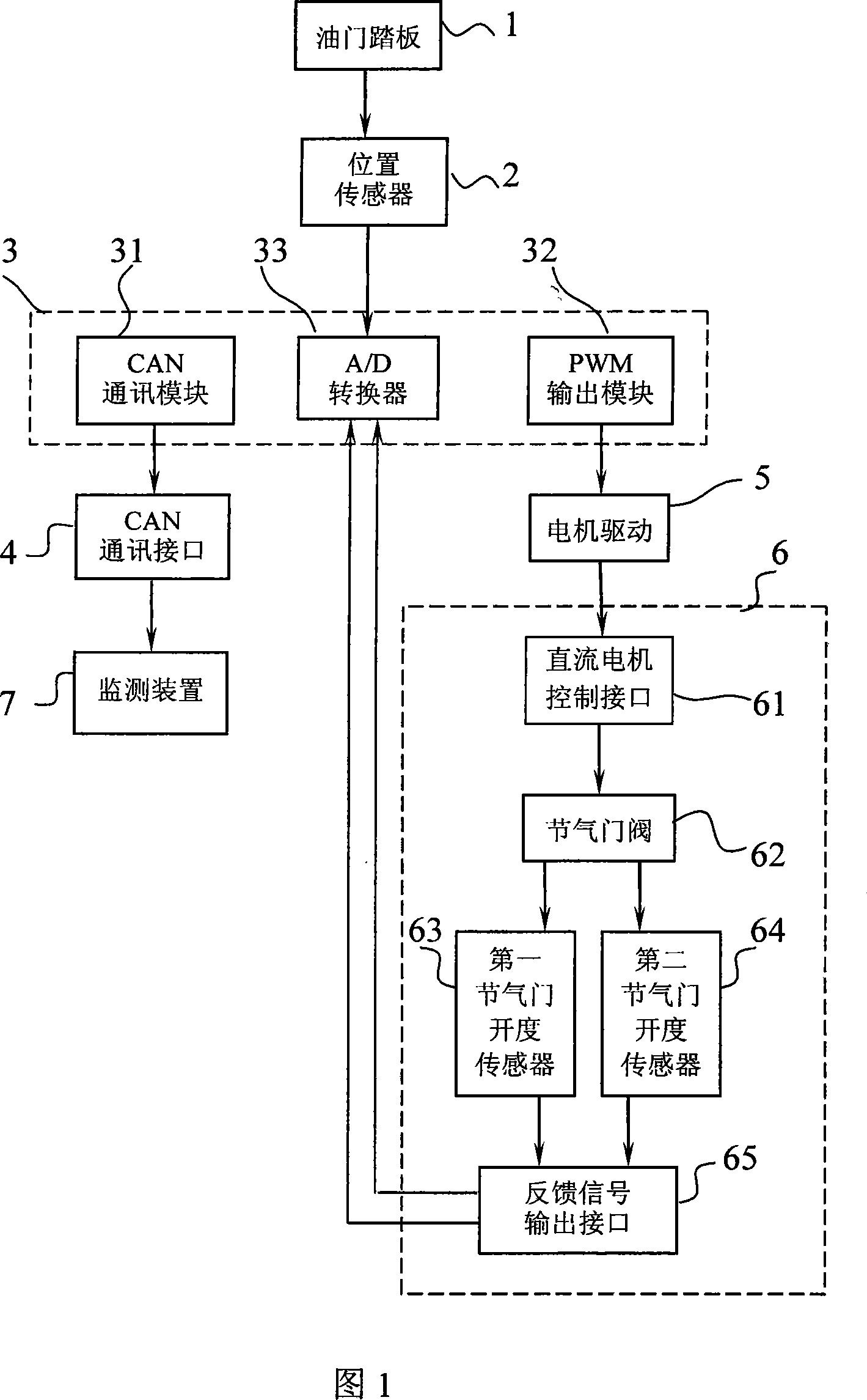
[0040] As shown in Figure 1, the structure of the automobile engine electronic throttle control system of the present invention is: the CAN communication control module 31 in the single-chip microcomputer 3 transmits the digitized signal after processing to the monitoring device 7 through the CAN communication interface 4; the PWM in the single-chip microcomputer 3 The output module 32 is connected with the motor drive circuit 5, and passes through the DC motor control interface 61 in the throttle body 6, the throttle valve 62, the two throttle opening sensors 63, 64, and the feedback signal output interface 65 in sequence, and finally the two groups of The throttle opening data feedback signal is delivered to the A / D converter 33 respectively, that is: the A / D converter embedded in the single-chip microcomputer 3 and the signal proces...


PUM


Abstract

The invention discloses a reliable electronic throttle control system with high position precision, high output force linearity and high response speed for an automotive engine. The invention comprises a power supply, a position transducer and an SCM both of which are connected with an accelerator pedal in turn; an A / D transducer, a PWM output module and a CAN communication control module, which are embedded inside SCM. The CAN communication control module transmits processed digitized signal to a monitoring plant through a CAN communication interface. The PWM output module is connected with a motor drive circuit, transmits the feedback signal of opening of two throttles to the A / D transducer through the throttle bodies; the throttle comprises a DC motor, a throttle valve, two throttle opening sensors, a return spring device and a feedback signal output interface, which are sealed into one piece. The DC motor is connected with the throttle valve through the control interface of the DC motor. The opening signal of the throttle valve is transmitted through the opening sensor of the throttle valve and is fed to the A / D transducer through the feedback information output interface. The direction of the spring force of the return spring always faces towards the closing direction of the throttle valve.

Description

technical field [0001] The invention relates to a control system and a control method for an automobile throttle, in particular to a control system and a control method for an automobile electronic throttle. Background technique [0002] The engine throttle regulating mechanism in the prior art mainly includes two structures of non-electric control and electric control. [0003] The engine non-electric throttle adjustment mechanism is composed of an accelerator pedal with a fixed shaft and a stay wire, one end of the stay wire is connected with the accelerator pedal, and the other end of the stay wire is connected with the engine throttle pull rod. During operation, step on the accelerator pedal with your feet, and pull the accelerator rod through the accelerator cable. The displacement of the throttle rod is also different according to the force of the driver. Therefore, the opening degree of the engine throttle is also different due to the cooperation of the return spring...

Claims


Application Information

Patent Timeline
IPC IPC(8): F02D41/26
Inventor 乔胜华冯琦李广霞陈弘
Owner CATARC AUTOMOTIVE TEST CENT TIANJIN CO LTD