
Small-sized hot air engine

A heat engine and small-scale technology, which is applied in the direction of heat variable displacement engine devices, mechanical equipment, machines/engines, etc., can solve the problems of complex structure and high cost of use, and achieve the effects of low manufacturing cost, low cost of use and simplified structure

Inactive Publication Date: 2008-07-09
SHANGHAI MICROPOWERS
View PDF0 Cites 3 Cited by
  • Summary
  • Abstract
  • Description
  • Claims
  • Application Information

AI Technical Summary

Problems solved by technology

[0005] The purpose of the present invention is to provide a small heat engine, which solves the technical problem that the traditional heat engine structure is not suitable for the small heat engine due to its complex structure, high manufacturing and use costs. It has the advantages of simple structure, easy manufacture, small volume, Features of light weight, low cost, easy maintenance and high reliability

Method used


Image

  • Small-sized hot air engine
  • Small-sized hot air engine
  • Small-sized hot air engine

Examples


Embodiment Construction

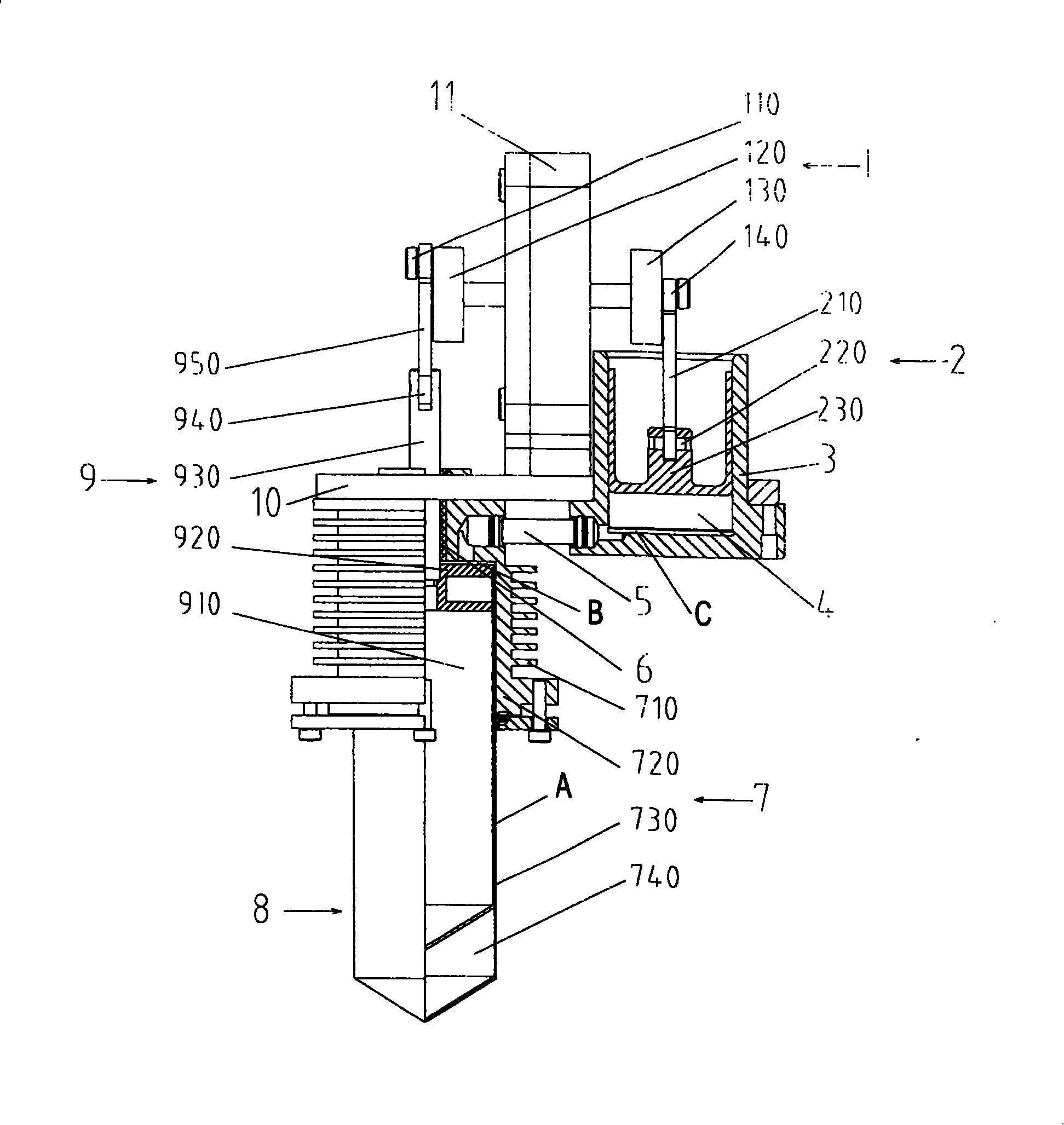
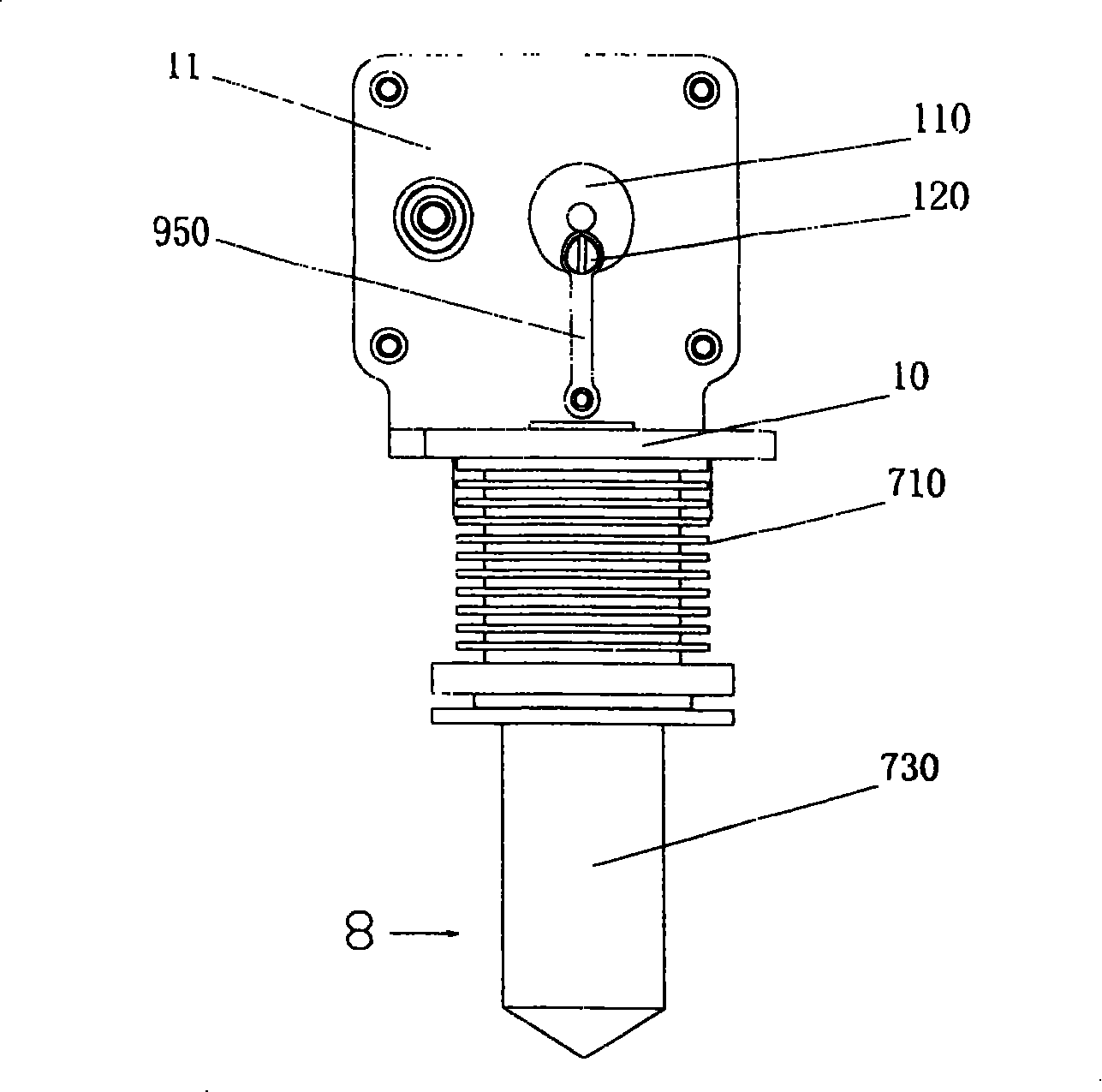
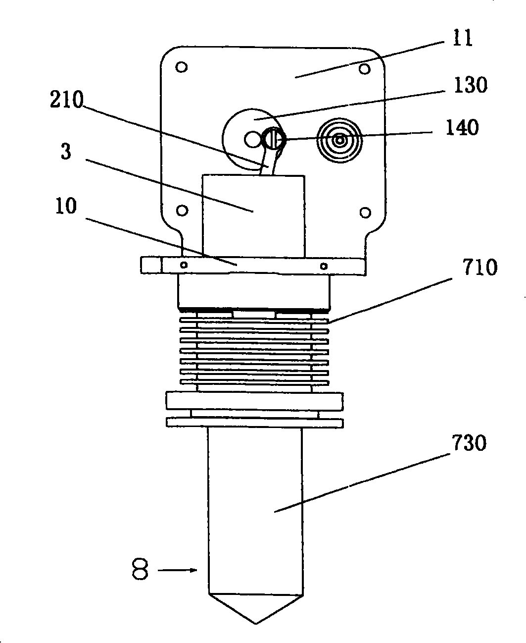
[0022] figure 1 , 2 and 3 show an embodiment of the present invention. Its structure is, comprises fuselage or machine body 10, power piston group 2, distributing piston group 9, heater 8, cooler 710, regenerator, output shaft 1 with two crank throws etc., distributing piston group 9. The power piston group 2 is rotatably connected to the output shaft 1 through the short connecting rod 950 and the long connecting rod 210 respectively, and is arranged on the same side of the output shaft 1, and the cooling valves are arranged on the outside of the gas distribution cylinder 740 from top to bottom in sequence. 710, regenerator and heater 8, the air distribution cylinder 740 and the power cylinder 4 are communicated through the air channel 5, near the top dead center of the movement of the air distribution piston group 9, a heater 8 is arranged outside the cylinder liner 730 for controlling The working fluid is heated. The hot air machine often uses hot air as the working mediu...


PUM


Abstract

The invention discloses a minitype heat engine, which comprises an engine body, a power piston group reciprocating in an actuating cylinder, a distribution piston group reciprocating in a distribution cylinder, a heater, a regenerator, a cooler, an output shaft with two bellcranks and a heating device for heating the heater. The power piston group is flexibly connected with the second bellcrank through a long connecting rod. The distribution piston group is flexibly connected with the first bellcrank through a short connecting rod. The actuating cylinder and the distribution cylinder arranged on one side of the output shaft. The end of the actuating cylinder approaching an upper dead point is connected with the end of the distribution cylinder approaching a lower dead point through a passage. The phase aberration of the first bellcrank and the second bellcrank of the output shaft is 90 degrees or 270 degrees. The regenerator consists of the fit clearances between distribution pistons and distribution cylinder liners. The heat engine has the advantages of simple structure, easy manufacturing, small size, light weight, low cost, convenient maintenance and high reliability, thus the heat engine is particularly applicable to minitype heat engines below 100W.

Description

technical field [0001] The invention relates to a heat engine, in particular to an external-combustion small heat engine. Background technique [0002] The heat engine, also known as the Stirling engine, is an external combustion engine heated by an external heat source. It is mainly composed of a heating system, a working medium circulation system, and a transmission system. Components and gas distribution piston components are the key parts that constitute the circulation system of the heat engine. The heat generated by the heating system is transferred to the internal working medium of the heat engine through the heater, and through the Stirling cycle, the piston is pushed to do work, and the heat is passed through the crankshaft of the transmission system. Or the output shaft is output externally. The regenerator is equivalent to an accumulator, which is used to absorb or release the heat of the working fluid in the Stirling cycle; the heater is used to heat the working...

Claims


Application Information

Patent Timeline
IPC IPC(8): F02G1/043F02G1/057F02G1/055F02G1/053
Inventor 忻晟李振中潘卫明
Owner SHANGHAI MICROPOWERS
Learn More