Single straight tube Coriolis mass flowmeter

A mass flow meter, single straight tube technology, applied in the direction of direct mass flow meter, mass flow measurement device, etc., can solve the problems of unfavorable emptying and cleaning, large fluid pressure loss, heavy workbench, etc., to simplify the structure, reduce Fluid pressure loss, overall volume reduction effect

Inactive Publication Date: 2008-07-16
TSINGHUA UNIV
View PDF0 Cites 10 Cited by
  • Summary
  • Abstract
  • Description
  • Claims
  • Application Information

AI Technical Summary

Problems solved by technology

[0004] (2) The self-vibration of the straight-tube measuring tube has higher requirements on the vibration reduction of the workbench, so generally the workbench is relatively heavy
[0005] (3) Although the U-shaped measuring tube has lower requirements on the vibration reduction of the workbench, its structure is relatively complex, its volume is large, and its fluid pressure loss is large, which is not conducive to emptying and cleaning

Method used


Image

  • Single straight tube Coriolis mass flowmeter

Examples


Embodiment 1

[0038] Embodiment 1, calibration experiment: the calibration method and process before the first use of the present invention.

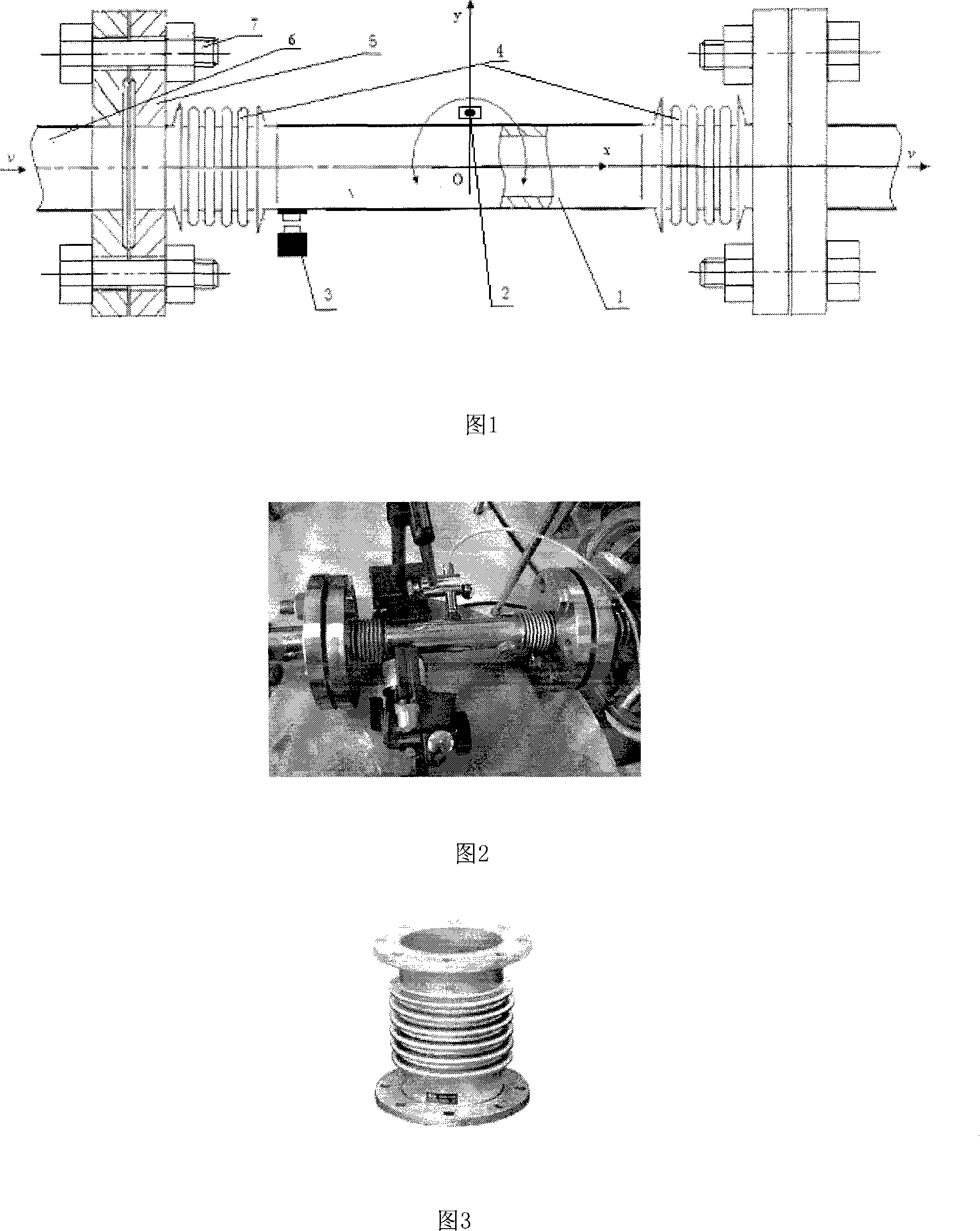
[0039] As shown in Figure 2, the experimental parameters: the amplitude of the excitation signal is 10V; the amplification factor of the power amplifier is 7; the distance between the excitation coil and the magnet sheet is about 3mm; the distance between the displacement sensor probe and the copper sheet is about 3mm.

[0040] When the pipe is filled with still water, sweep frequency excitation. The mode shape of the system is obtained: the first natural frequency is 78Hz, the second natural frequency of the system is 138Hz, and the vibration amplitude of the center of the measuring tube (that is, the center of mass) is represented by an electrical signal as 12mv.

[0041] Experimental steps:

[0042] (1) Install and fix the flowmeter. Connect the flanges at both ends of the flowmeter to the water pipe under test, fix them with bolts, and check wh...

Embodiment 2

[0052] Embodiment 2, test example: use the present invention to measure the mass flow in the water pipe of a certain fluid experiment platform.

[0053]On the basis of the calibration experiment, start the switch of the exciter, set the excitation frequency of the system as the second-order natural frequency of the system, when the measured fluid passes through the flowmeter measuring tube with full load, after the system is stable, read The value of the detector is then measured.

[0054] Experimental steps:

[0055] (1) Connect and install the flowmeter, and check that the seal is intact.

[0056] (2) Adjust the excitation frequency of the flowmeter vibrator (3) to 138Hz.

[0057] (3) Open the valve of the delivery pipeline (6) of the fluid to be measured, so that the full load of water flows through the measuring tube.

[0058] (4) The vibration amplitude of the center of the measuring tube is measured, that is, the electrical signal is obtained from the oscilloscope of ...


PUM


Abstract

The invention relates to a Coriolis mass flow meter, belonging to the technical field of test and measuring instrument. The invention comprises a measuring tube (1), an inspecting device (2), an exciting device (3), a wave tube (4), a connection flange (5), a feeding pipe (6) of the liquid to be measured and a connection bolt (7). Two ends of the measuring tube (1) are respectively connected with the wave tube (4), and the other two ends of each wave tube (4) are respectively connected two connection flanges (5), and the connection flange is connected with the feeding pipe (6) of the liquid to be measured through the connection bolt (7). The inspecting device (2) and the exciting device (3) are respectively arranged at the positions 3 to 5mm from the center of the measuring tube (1) and the outer tube wall at one end, and the three parts are on the same plane. Arranging the invention has the proposals that the exciting frequency is set as a second-step stationary frequency; the liquid mass flow is obtained by a central swing inserted value of the fully loaded measuring tube. The invention enlarges the material range of the measuring tube so as to reduce manufacturing cost, and reduces integrated volume and liquid pressure loss.

Description

technical field [0001] The invention is a Coriolis mass flowmeter, which belongs to the technical field of testing and measuring instruments. Background technique [0002] The current Coriolis mass flowmeter measurement principle is generally to use the alloy elastic tube fixed at both ends to bend and vibrate, and the fluid flows through the tube to generate Coriolis forces in different directions to change the resonance state of the tube, and to detect the measurement at both ends of the alloy elastic tube. The amount of change in vibration at a point is measured. However, the main disadvantages of these types are generally as follows: [0003] (1) Generally, high-priced titanium alloys are used as elastic tubes. [0004] (2) The self-vibration of the straight tube type measuring tube has higher requirements on the vibration reduction of the workbench, so generally the workbench is relatively heavy. [0005] (3) Although the U-shaped measuring tube has lower requirement...

Claims


Application Information

Patent Timeline
Patent Type & Authority Applications(China)
IPC IPC(8): G01F1/84
Inventor 张小章徐伟国
Owner TSINGHUA UNIV
Why Eureka
Try Eureka