Driving device and driving method thereof

A driving device and driving signal technology, applied in cathode ray tube indicators, digital-to-analog converters, instruments, etc., can solve problems such as affecting product competitiveness, speeding up stabilization time, operational amplifier oscillation, etc., to achieve the effect of shortening stabilization time

Active Publication Date: 2008-07-16
NOVATEK MICROELECTRONICS CORP
View PDF0 Cites 9 Cited by
  • Summary
  • Abstract
  • Description
  • Claims
  • Application Information

AI Technical Summary

Problems solved by technology

[0010] In order to shorten the stable time of the output voltage transition of the operational amplifier, if the compensation capacitor is reduced, since the transition time of the output voltage of the operational amplifier is proportional to the compensation capacitor, the smaller the compensation capacitor, the shorter the transition time of the output voltage of the operational amplifier, but It is easy to cause the operational amplifier to oscillate
If the current of the operational

Method used


Image

  • Driving device and driving method thereof
  • Driving device and driving method thereof
  • Driving device and driving method thereof

Examples


Example Embodiment

[0081] For the convenience of description, the driving devices described in the following embodiments are all source driving devices for driving the liquid crystal panel, but they are not intended to limit the application of the present invention.
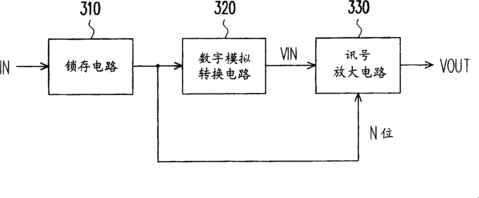
[0082] image 3 It is a block diagram of a driving device according to an embodiment of the present invention. Figure 4 It is a flowchart of a driving method according to an embodiment of the present invention. Please refer to according to the needs of the description image 3 versus Figure 4 .image 3 It includes a latch circuit 310, a digital-to-analog conversion circuit 320, and a signal amplifying circuit 330. The latch circuit 310 receives the digital data IN and outputs it after latching the digital data IN (such as Figure 4 Step 410). The digital-to-analog conversion circuit 320 receives the digital data IN output by the latch circuit 310, and converts the digital data IN into an analog signal VIN (such as Figure 4 Step 420...


PUM


Abstract

The invention provides a driving device and a driving method thereof. The driving device comprises a digital-analog conversion circuit and a signal amplifying circuit, wherein, the digital-analog conversion circuit is used to receive digital data and converts the digital data into an analog signal; the signal amplifying circuit is coupled with the digital-analog conversion circuit for receiving the analog signal to generate a driving signal and dynamically changing the driving capability of the driving signal according to at least one bit in the digital data.

Description

technical field [0001] The invention relates to a driving device and a method for generating a driving signal, in particular to a driving device capable of reducing power consumption and a method for generating a driving signal. Background technique [0002] The characteristics of liquid crystal molecules cannot be fixed at a certain voltage all the time. Otherwise, even if no voltage is applied to the liquid crystal molecules for a long time, the liquid crystal molecules will be destroyed due to their characteristics, so that they can no longer respond to changes in the electric field. Rotate to form different gray scales. Therefore, it is necessary to drive the liquid crystal in an AC mode to avoid the destruction of the characteristics of the liquid crystal molecules. Reverse rotation. [0003] There are two types of AC driving methods, one is a driving method in which the common voltage (generally referred to as Vcom) is fixed, and the other is a driving method in whic...

Claims


Application Information

Patent Timeline
IPC IPC(8): G09G3/20G09G3/36G09G5/02H03M1/66G02F1/133H03F3/45
Inventor 许民杰宋光峰
Owner NOVATEK MICROELECTRONICS CORP
Why Eureka
Try Eureka