
Water content detection sensor

A technology for detecting sensors and moisture, applied in the direction of material resistance, absorbing pads, etc., can solve problems such as poor electrodes, malfunctions, and inability to judge whether the circuit is normal or not, and achieve the effect of improving sensitivity and accuracy

Inactive Publication Date: 2008-07-16
UNI CHARM CORP
View PDF3 Cites 2 Cited by
  • Summary
  • Abstract
  • Description
  • Claims
  • Application Information

AI Technical Summary

Problems solved by technology

[0006] In the conventional moisture detection sensor, a potential difference is generated between the electrodes, and if moisture adheres between the electrodes and a current flows, a signal indicating that moisture is generated is output, so it is impossible to judge whether the circuit including the electrodes is normal or not.
Therefore, although moisture adheres between the electrodes, there is a problem that no signal is generated due to poor electrodes, etc., and the occurrence and existence of moisture cannot be detected.
[0007] In addition, when the conventional moisture detection sensor is used to detect urination in diapers, etc., there is a problem that if it is attempted to detect urination many times, the resistance value changes, which is likely to cause a problem of malfunction.

Method used


Image

  • Water content detection sensor
  • Water content detection sensor
  • Water content detection sensor

Examples


Embodiment approach 1

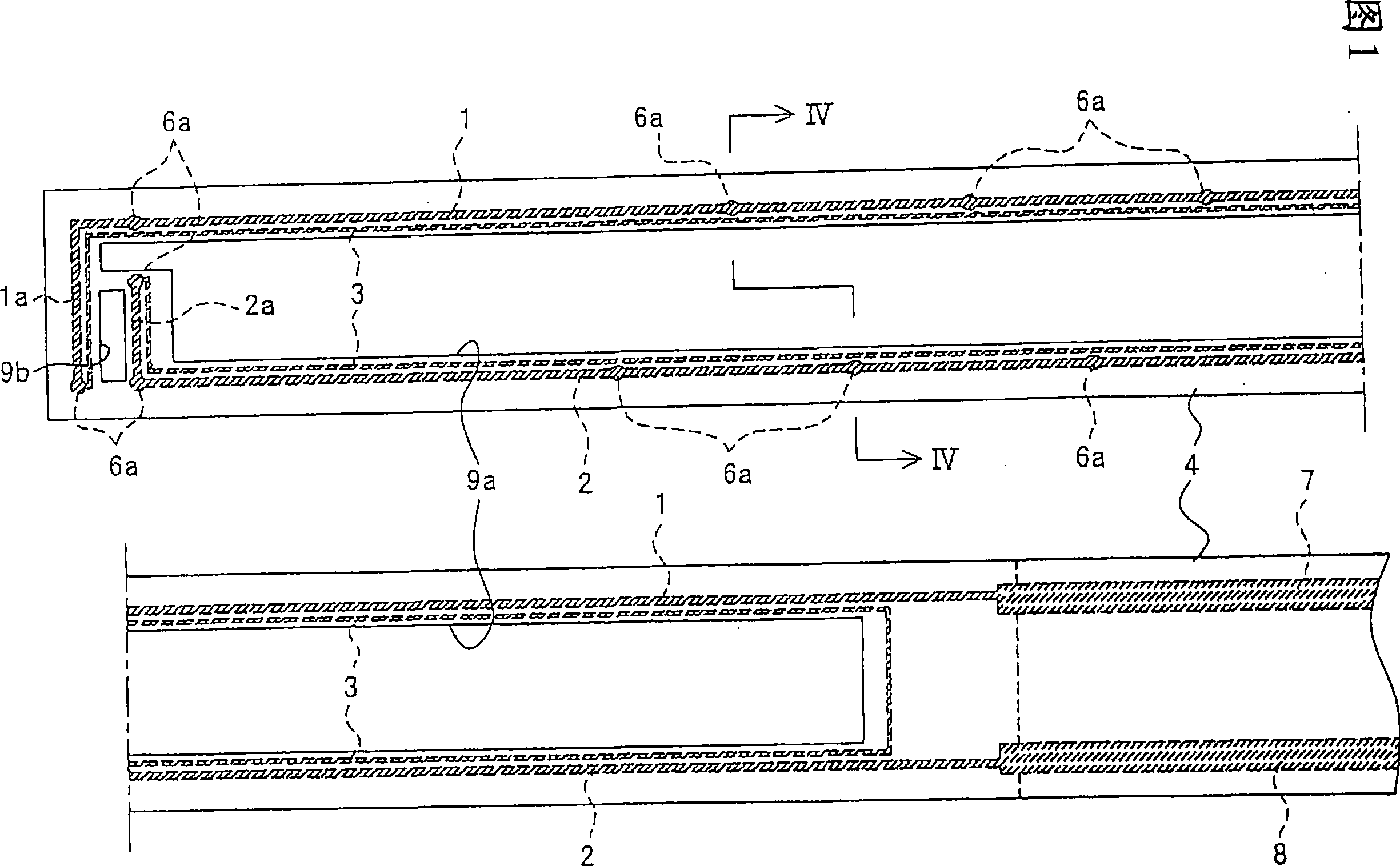
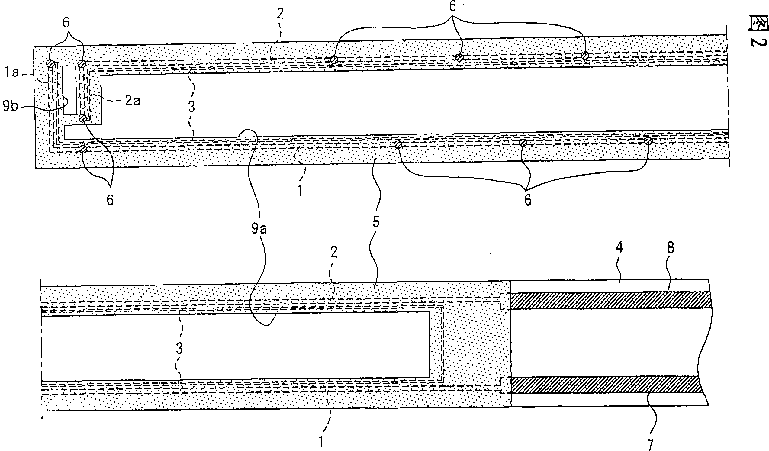
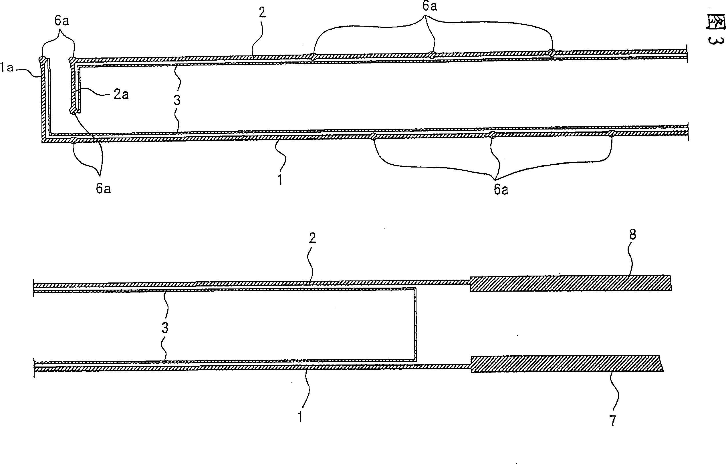
[0036] As shown in FIGS. 1 to 4 , the moisture detection sensor has a circuit portion including low-resistance wires 1 and 2 extending in parallel and a high-resistance wire 3 connecting ends of the low-resistance wires 1 and 2 . The circuit portion is sandwiched between the waterproof and insulating carrier 4 and the cover 5 , and exposure holes 6 are formed in the cover 5 through which the low-resistance lead wires 1 and 2 are exposed in multiple places.

[0037] The carrier 4 is an integral member that supports the moisture detection sensor, and is formed in a freely bending belt shape. The carrier 4 has water repellency so that moisture does not pass through, and has insulation so that electricity does not conduct. In addition, in order to easily check whether the circuit part is normal or not, it is desirable to form it transparently. The carrier 4 is made of a biaxially stretched film of polypropylene, polyethylene, polyvinyl chloride, polyester, polyamide, polyimide, p...

Embodiment approach 2

[0053] In this second embodiment, as shown in FIG. 5 , the high-resistance lead wire 10 of the circuit portion of the moisture detection sensor is formed shorter than that of the first embodiment.

[0054] In addition, the same code|symbol is used for the same part as Embodiment 1, and the overlapping description is abbreviate|omitted.

Embodiment approach 3

[0056] In this Embodiment 3, as shown in FIG. 6, the high-resistance wire 11 of the circuit portion of the moisture detection sensor is formed shorter than that of Embodiments 1 and 2, and at one end of the two low-resistance wires 1, 2 between them, extending linearly.

[0057] In addition, the same parts as those in Embodiments 1 and 2 are denoted by the same symbols, and overlapping descriptions are omitted.


PUM

PropertyMeasurementUnit
thicknessaaaaaaaaaa
electrical resistanceaaaaaaaaaa

Abstract

In the present invention, the circuit part containing the low-resistance wires (1, 2) extending in parallel and the high-resistance wire (3) connecting the ends of the low-resistance wires is sandwiched between the waterproof and insulating carriers ( 4) and the covering body (5), exposing holes (6) for exposing low-resistance wires over a plurality of places are formed in the covering body. When the current flows in the circuit part, if moisture adheres between the exposed holes and short-circuits between the low-resistance wires, the current value increases compared to before the moisture adheres, and the circuit is judged to be normal when a small current flows. , if a short circuit occurs and a large current flows, it is judged that moisture is generated. Whether the moisture detection sensor is normal or not can be judged in advance.

Description

technical field [0001] The present invention relates to a moisture detection sensor. Background technique [0002] Conventionally, when moisture adheres between electrodes and a current flows, moisture detection sensors are known that detect the presence and generation of moisture (for example, refer to Patent Documents 1, 2, and 3). This moisture detection sensor is used, for example, in automatic wipers of automobiles and diapers. [0003] Patent Document 1: JP-A-63-290950 [0004] Patent Document 2: JP-A-2000-19136 [0005] Patent Document 3: JP-A-2002-82080 [0006] Conventional moisture detection sensors generate a potential difference between electrodes, and if moisture adheres between the electrodes and current flows, a signal indicating that moisture is generated is output. Therefore, it is impossible to determine whether the circuit including the electrodes is normal or not. Therefore, although moisture adheres between the electrodes, there is a problem that no ...

Claims


Application Information

Patent Timeline
Patent Type & Authority Applications(China)
IPC IPC(8): G01N27/04
CPCA61F13/42
Inventor 和田一郎铃木未央户田清志平井裕一林正保植松裕上西利彦
Owner UNI CHARM CORP
Learn More