Elevator traction machine

An elevator traction machine and traction sheave technology, applied in the field of elevator traction machines, can solve the problems of deterioration of casting quality, increased material waste, large wall thickness, etc., to reduce processing steps and difficulty, improve casting quality, and ensure operation. safe effect

Inactive Publication Date: 2008-07-23
NINGBO HONGDA ELEVATOR
View PDF1 Cites 8 Cited by
  • Summary
  • Abstract
  • Description
  • Claims
  • Application Information

AI Technical Summary

Problems solved by technology

To sum up, from the perspective of mechanical structure, the wall thickness of the outer rotor cylinder of the elevator traction machine in the prior art is relatively large, which not only leads to the deterioration of the casting quality caused by the increase in the weight of the single casting, but also affects the operation of the equipment. Safety, and because the outer rotor cylinder has to use relatively high-priced wear-resistant materials as a whole, its manufacturing cost is also significantly increased
[0009] 2. When the outer rotor cylinder of the above prior art is used as a traction sheave, it is a vulnerable part. Once the traction groove of the outer rotor cylinder is worn to the allowable limit, the entire outer rotor cylinder must be replaced, even if The permanent magnetic block pasted on its inner surface has

Method used


Image

  • Elevator traction machine
  • Elevator traction machine
  • Elevator traction machine

Examples


Embodiment Construction

[0025] The present invention will be further described below in conjunction with the accompanying drawings and specific embodiments.

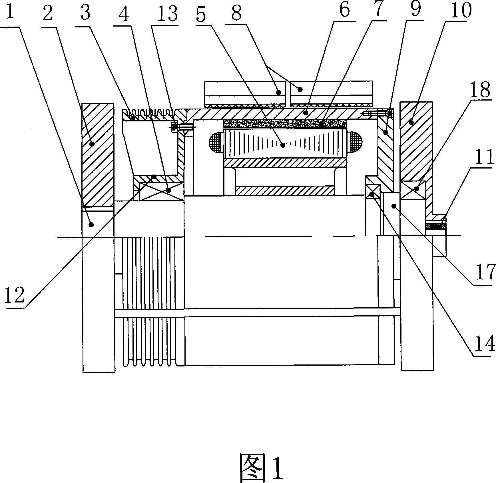
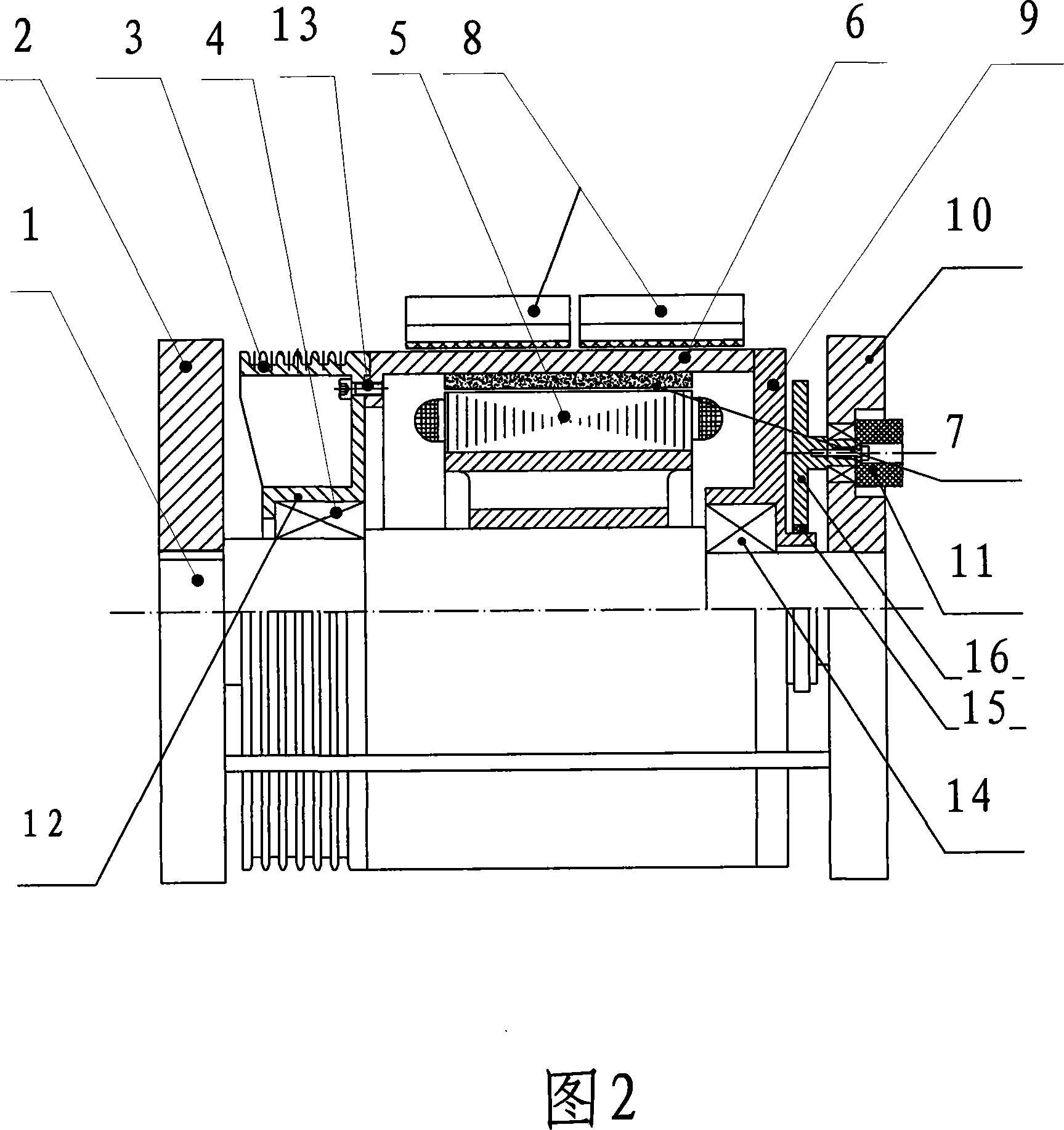
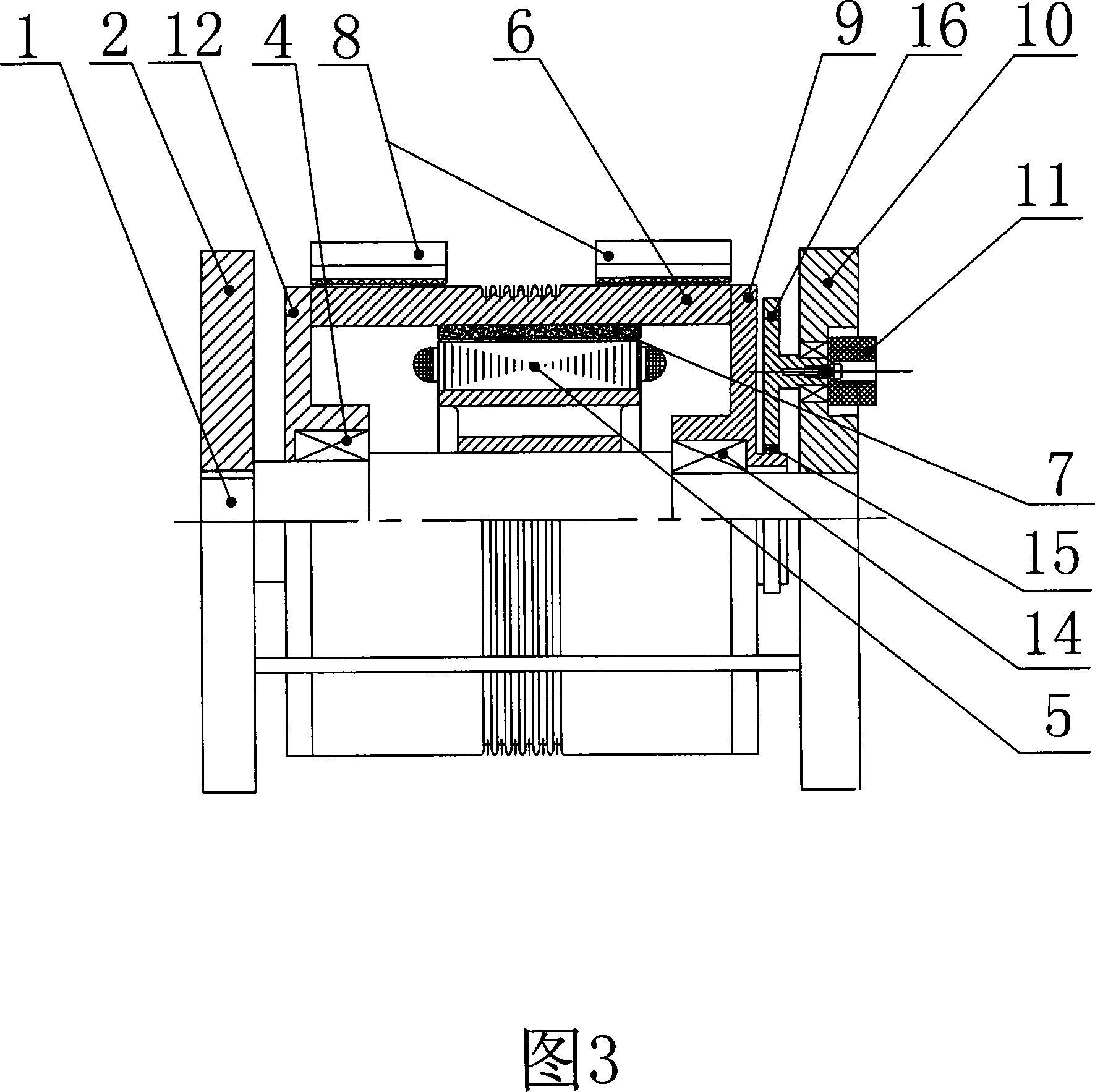
[0026]Figure 2 shows an embodiment of the elevator traction machine of the present invention, including a detachable load-bearing wallboard frame composed of a front support 2 and a rear support 10, a support shaft 1, a stator 5 fixed on the support shaft 1, The outer rotor cylinder 6, which rotates outside the stator 5 and doubles as a brake wheel, and the encoder 11 for measuring the speed and the relative position of the stator and rotor magnetic fields. The inner surface of the outer rotor cylinder 6 is mounted with a permanent magnet 7, and the two ends of the outer rotor cylinder 6 are respectively fixed with a front end cover 12 and a rear end cover 9, and the front end cover 12 and the rear end cover 9 are supported by bearings. On the support shaft 1, the front end of the support shaft 1 is fixed on the front support 2, and the rear en...


PUM


Abstract

The invention discloses an elevator traction device, which includes a detachable load-bearing wall frame body that consists of a front support (2) and a rear support (10), a supporting shaft (1), a stator (5) fixedly arranged on the supporting shaft (1), an outer rotor cylinder (6) sheathed outside the stator (5), a permanent magnetic piece (7)and an encoder (11); a traction wheel (3) is separably connected with the end of the outer rotor cylinder (6) and is arranged on the support shaft (1) by a bearing, one end of the supporting shaft is fixed on the front support (2) and the other end supports on a rear end cover (9) by a bearing (14), a rotation shaft (17) is tightly fitted in a central hole that is on the rear end cover and is coaxial with the support shaft (1), and the other end of the rotation shaft (17) is arranged on the rear support (10) by a bearing (18) and is connected with the encoder (11). The invention is low in manufacturing cost and maintenance cost, safe in operation, and good in maintainability and a cage almost has no vibration.

Description

technical field [0001] The invention relates to an elevator matching device, in particular to an elevator traction machine. Background technique [0002] As elevators are used more and more widely, people's requirements for elevators are getting higher and higher. The elevator traction machine is one of the key devices that affect the operation of the elevator. [0003] The applicant's prior invention patent application published on the website of the State Intellectual Property Office of China, whose publication number is CN 1746096A, discloses a kind of elevator traction machine (see Figure 3): it is based on two opposite load-bearing wall panels as Front support 2 and rear support 10, the four corners of front support 2 and rear support 10 are equipped with detachable pull rods, fastened with nuts, thereby connecting to form the load-bearing structure of cube structure. Brake 8 is installed on the pull rod. A support shaft 1 is installed and fixed in the central axis h...

Claims


Application Information

Patent Timeline
IPC IPC(8): B66B11/04
Inventor 潘式正胡畅
Owner NINGBO HONGDA ELEVATOR
Why Eureka
Try Eureka