Flow turning-back gas liquid cross-flow super-gravitational field revolving bed equipment

A super-gravity field, baffled technology, applied in chemical/physical/physical-chemical mobile reactors, fractionation, etc., can solve the problems of ineffective use of space, small gas flow area, small gas-liquid flow, etc. Reduced energy consumption, reasonable structure and small gas resistance

Active Publication Date: 2008-07-30
ZHEJIANG UNIV OF TECH
View PDF5 Cites 6 Cited by
  • Summary
  • Abstract
  • Description
  • Claims
  • Application Information

AI Technical Summary

Problems solved by technology

Although the rotating bed has a high mass transfer capacity, it also has its own weaknesses. Because the rotor adopts a structure combining dynamic and static parts, the liquid has experienced multiple static-acceleration processes in the rotor, so the energy consumption of the rotor rotation On the other hand, since half of the space inside the rotor is a non-mass transfer area, the flow area of ​​the g

Method used


Image

  • Flow turning-back gas liquid cross-flow super-gravitational field revolving bed equipment
  • Flow turning-back gas liquid cross-flow super-gravitational field revolving bed equipment
  • Flow turning-back gas liquid cross-flow super-gravitational field revolving bed equipment

Examples


Example Embodiment

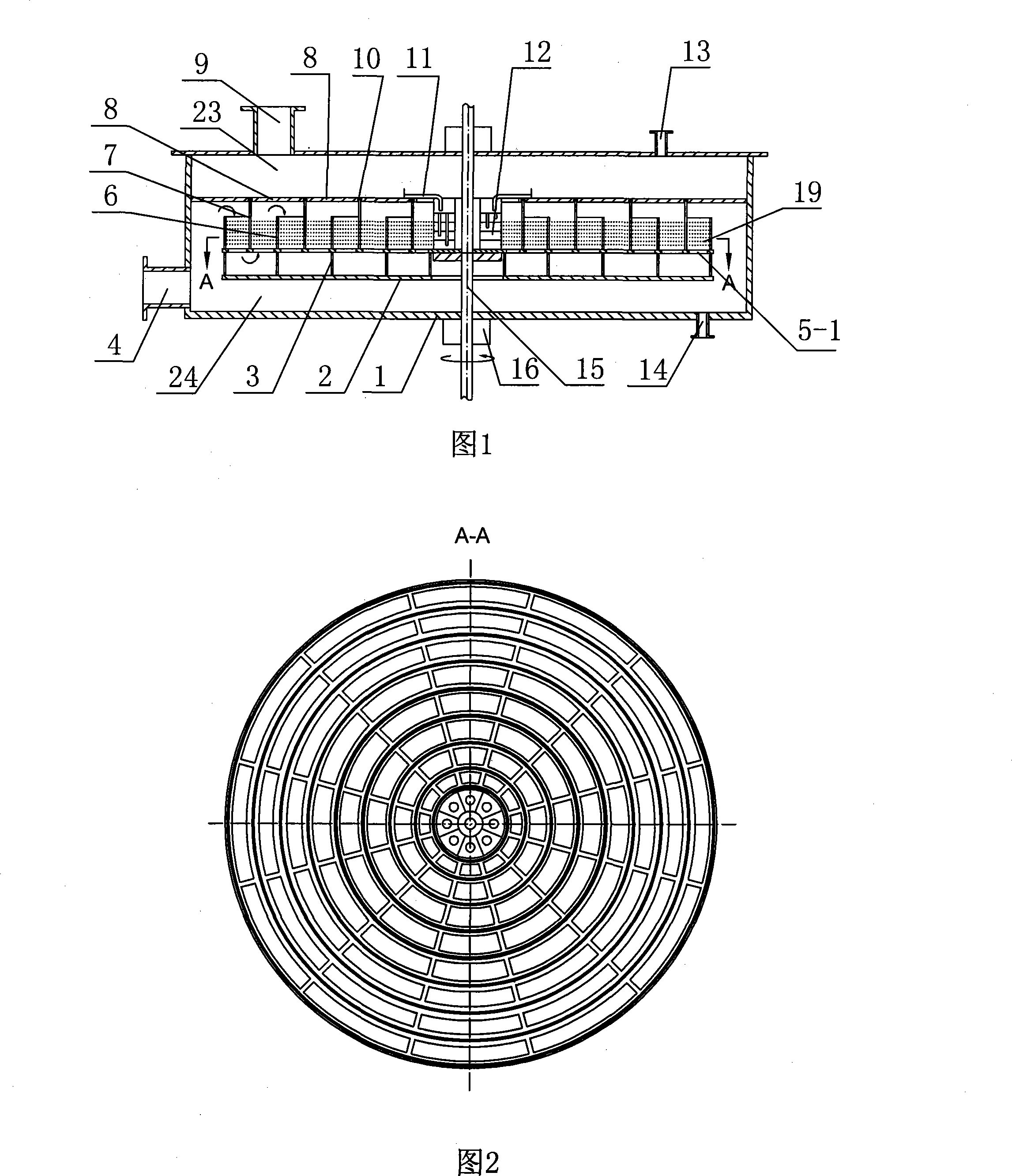
[0017] Embodiment 1: single-layer structure

[0018] As shown in Figures 1 and 2, this baffled gas-liquid cross-flow type supergravity field rotating bed device mainly includes a shell 1, a gas inlet 4, a gas outlet 9, a catheter 11, a liquid distributor 12, The liquid inlet 13 , the liquid outlet 14 and the rotating shaft 15 , and the connection between the rotating shaft 15 and the housing 1 is provided with a mechanical seal 16 . The housing 1 is divided into an upper chamber 23 and a lower chamber 24 by a static plate 8, and the housing 1 is provided with a gas inlet 4, a liquid outlet 14, a gas outlet 9 and a liquid inlet 13, wherein the gas outlet 9 and the liquid inlet 13 are respectively It communicates with the upper cavity 23, and the gas inlet 4 and the liquid outlet 14 communicate with the lower cavity 24 respectively; the rotating shaft 15 runs through the housing 1, and the rotor is fixedly connected with the rotating shaft 15. Disk concentric circle 3, short co...

Example Embodiment

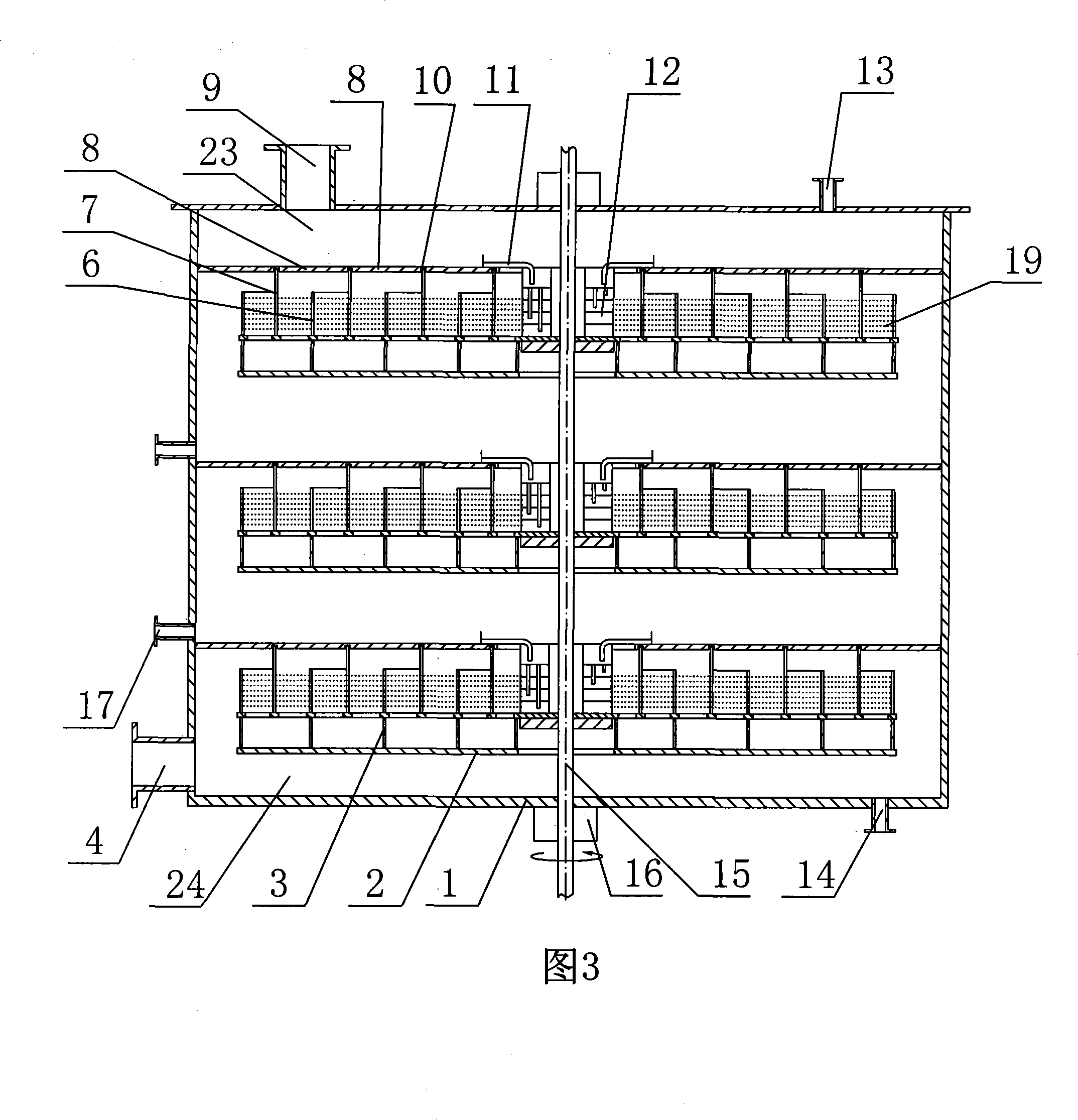
[0021] Embodiment 2: multi-layer structure

[0022] As shown in Figure 3, the housing 1 is divided into an upper cavity 23, a multi-layer intermediate cavity 25 and a lower cavity 24 by a static plate 8, and the intermediate cavity 25 is provided with an intermediate feed port 17 to form a multi-layer folding stream structure. Multiple rotors are coaxially connected in series in a single housing. The gas-liquid flow in each rotor is the same as that of a single-layer structure. The difference is that the gas leaving the center of a certain layer of rotor will enter the outer edge of the adjacent upper layer of rotor again. , and then pass through the upper rotor along a tortuous path and then enter another layer of rotor on it; and the liquid that leaves this layer of rotor is collected and then enters the liquid distribution of the next layer of rotor through the catheter tube 11 of the adjacent next layer of rotor The device 12 passes through the next layer of rotors under ...

Example Embodiment

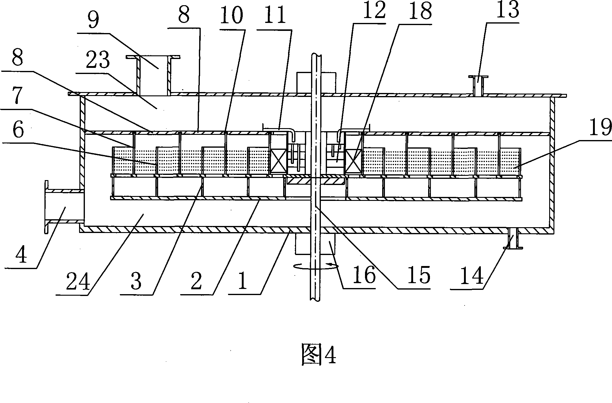
[0023] Embodiment 3: single-layer or multi-layer structure

[0024] As shown in Figure 4, when applied to gas-liquid mass transfer occasions, the last baffle area experienced by the gas at the center of each rotor layer can be filled with packing 18, which can effectively prevent mist entrainment.


PUM


Abstract

The invention relates to a rotating bed of overweight field of baffled gas-liquid cross flowing type. The shell of the invention is divided into an upper cavity and a lower cavity by a static disc; a gas outlet and a liquid inlet are respectively communicated with the upper cavity; the gas inlet and liquid outlet are respectively communicated with the lower cavity; a rotary shaft goes through the shell; the rotor consists of an upper movable disc, a lower movable disc, a concentric circle of the lower movable disc, a short concentric circle, a long concentric circle and a liquid distributor which are fixedly connected with the rotary shaft, wherein, the upper movable disc is provided with the slots for gas circulation; the long concentric circle is arranged between the upper movable disc and the static disc; the long concentric circle and the short concentric circle are crossly positioned; a first passage and a second passage are communicated through the upper movable disc slot to form a devious S-shaped baffled passage; the upper concentric circle and the lower concentric circle are provided with the small holes corresponding to the liquid outlet holes on the liquid distributor in axial direction; one end of a liquid guide pipe is communicated with the upper end of the liquid distributor while the other end with liquid inlet. The invention has the advantages of excellent mass transfer capability which reduces the rotational energy consumption and pressure.

Description

technical field [0001] The invention relates to a gas-liquid contact mass transfer device, in particular to a baffled gas-liquid cross-flow type supergravity field rotary bed device, which can be widely used in chemical, pharmaceutical, metallurgy, light industry and other industries for absorption, Occasions such as rectification, heat transfer, chemical reaction, and preparation of nanomaterials are especially suitable for gas absorption processes due to the extended path of the gas phase. Background technique [0002] Since its birth in the 1970s, hypergravity technology has been favored because it can greatly reduce the size of equipment. The earliest authorized patent on high-gravity technology is Professor Ramshaw's European patent EP0002568, the patent name is Mass transfer apparatus and its use, which discloses a packing type high-gravity field rotating bed (rotating packed bed), and many high-gravity technology later Patents such as ZL97212054.8, CN95214611.8, etc....

Claims


Application Information

Patent Timeline
IPC IPC(8): B01J19/28B01D3/30
Inventor 计建炳徐之超王广全焦云强
Owner ZHEJIANG UNIV OF TECH
Why Eureka
Try Eureka