Hydraulic cold drawn pipe machine

A pipe extruding machine and hydraulic technology, which is applied in the field of metal pipe cold drawing equipment, can solve the problems of high compressive strength and rigidity requirements, and achieve the effects of low cost, overcoming lateral movement and convenient installation.

Active Publication Date: 2008-07-30
CHANGZHOU LIAN HYDRAULIC EQUIP
View PDF1 Cites 8 Cited by
  • Summary
  • Abstract
  • Description
  • Claims
  • Application Information

AI Technical Summary

Problems solved by technology

[0003] The purpose of the present invention is to provide a practical solution for the current hydraulic cold-drawn pipe machine to be fixedly connected to the solid foundation of concrete casting through anchor bolts, and the foundation, anchor bolts, and bed durin

Method used


Image

  • Hydraulic cold drawn pipe machine
  • Hydraulic cold drawn pipe machine
  • Hydraulic cold drawn pipe machine

Examples


Embodiment Construction

[0028] The accompanying drawings disclose the specific structures of the embodiments of the present invention, and the present invention will be further described in detail below in conjunction with the accompanying drawings.

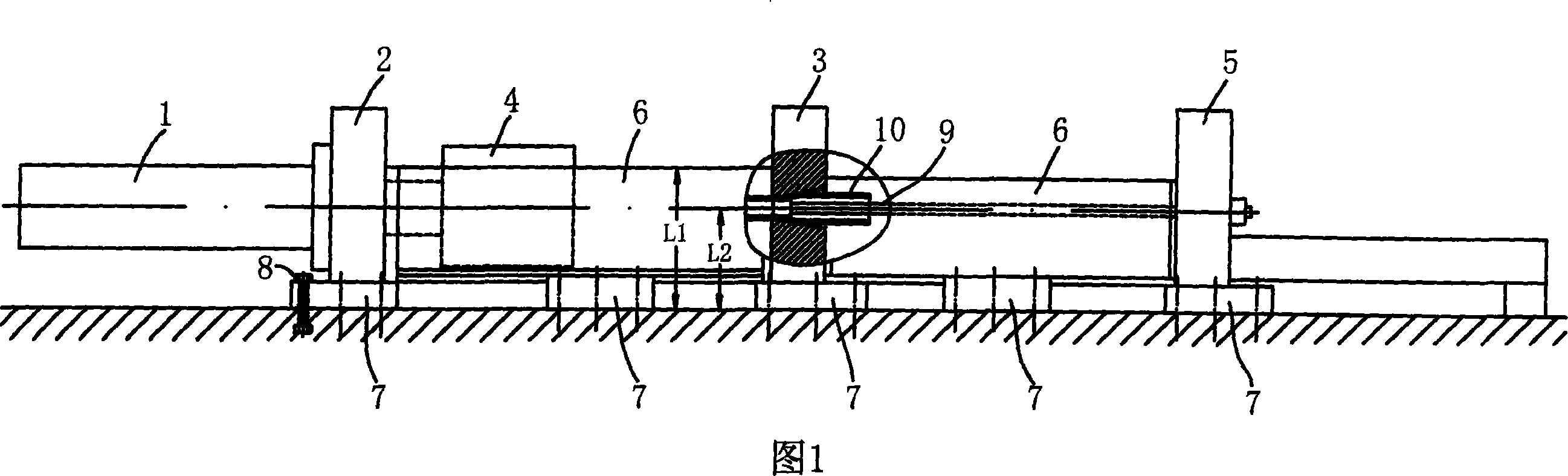
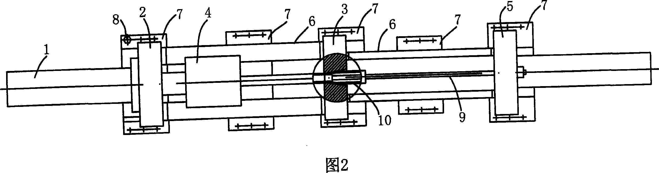
[0029] It can be seen from Fig. 1 and Fig. 2 that the hydraulic cold drawn pipe machine includes a main cylinder seat 2 for installing the main cylinder 1, and a drawing die seat 3 inside which can draw the drawn pipe blank 10 into a forming mold, and Located between the main cylinder base 2 and the drawing die base 3, there is a clamp trolley 4 driven by the main cylinder 1 and used to clamp the drawn tube blank 10, and the end is provided for penetrating The core rod seat 5 of the positioning core rod 9 is fixedly connected with two segmented independent bed bodies 6 between the main cylinder seat 2, the drawing die seat 3 and the core rod seat 5, the main oil cylinder seat 2, the drawing die The seat 3, the clamp trolley 4, the mandrel seat 5 and the...


PUM


Abstract

The invention discloses a hydraulic cold tube drawing bench, which comprises a main cylinder seat, a drawing die seat, a clamping dolly which is arranged between the main cylinder seat and the drawing die seat and is driven by a main cylinder, a core rod seat used for penetrating a positioning core rod, and an end which is fixedly connected with the main cylinder seat, the drawing die seat and the core rod seat sequentially on two independent section lathe beds; the main cylinder seat, the lathe bed, the drawing die seat, the lathe bed and the core rod seat are axially arranged. The invention is characterized in that: the lower parts of the main cylinder seat, the core rod seat and the lathe beds are all provided with lateral displacement limit devices containing concave positioning grooves; the concave positioning groove consists of a bottom plate and two side baffles or consists of L-shaped pieces formed by a bottom plate and side baffles and arranged symmetrically along the longitudinal axis. The lateral displacement limit devices are fixedly connected with groundwork. The invention has the advantages that: by using the simple structure, the invention effectively overcomes compression deformation of the lathe beds, and has low cost, convenient installment and low requirement for the ground which can be widely applied to metallurgical industry to reduce or expand pipe blanks.

Description

technical field [0001] The invention relates to a metal pipe cold drawing equipment used in the metallurgical industry, in particular to a hydraulic pressure cold drawing pipe machine which adopts a lateral displacement limiting device to prevent the lateral displacement of the fuselage during operation. Background technique [0002] In the metallurgical industry, the production of cold drawn metal pipes is the secondary processing of metal pipes after hot rolling and extrusion; the hydraulic cold drawn pipe machine is to make metal pipes such as hot rolled seamless metal pipes or straight seam welded pipes The finished pipes produced without cutting and precise wall thickness meet the actual needs; compared with the mechanical transmission cold drawing machine, the hydraulic cold drawing machine has high precision, large pulling force, low energy consumption, high production efficiency and The equipment has advantages such as simple structure, and is more and more widely us...

Claims


Application Information

Patent Timeline
IPC IPC(8): B21C1/22
Inventor 周新建
Owner CHANGZHOU LIAN HYDRAULIC EQUIP
Why Eureka
Try Eureka