Layered multitime pressure regulating pulp conditioning casting method

A secondary grouting and grouting technology, applied in the engineering field, can solve the problems of grout running out, enhance soil strength and density, reduce project investment, etc., and achieve highly targeted effects

Inactive Publication Date: 2008-07-30
山东省交通厅公路局 +1
View PDF0 Cites 30 Cited by
  • Summary
  • Abstract
  • Description
  • Claims
  • Application Information

AI Technical Summary

Problems solved by technology

[0003] In order to overcome the above-mentioned deficiencies in the prior art, the present invention can better study the grouting reinforcement method for the soil in a specific area, and avoid the blindness of construction. Developed areas, large porosity and other geological conditions of grout running out, grout leakage, so as to enhance the strength and density of soil in specific areas, significantly reduce project investment, save construction time, speed up construction progress and reduce environmental pollution. Regulating grouting grouting method

Method used

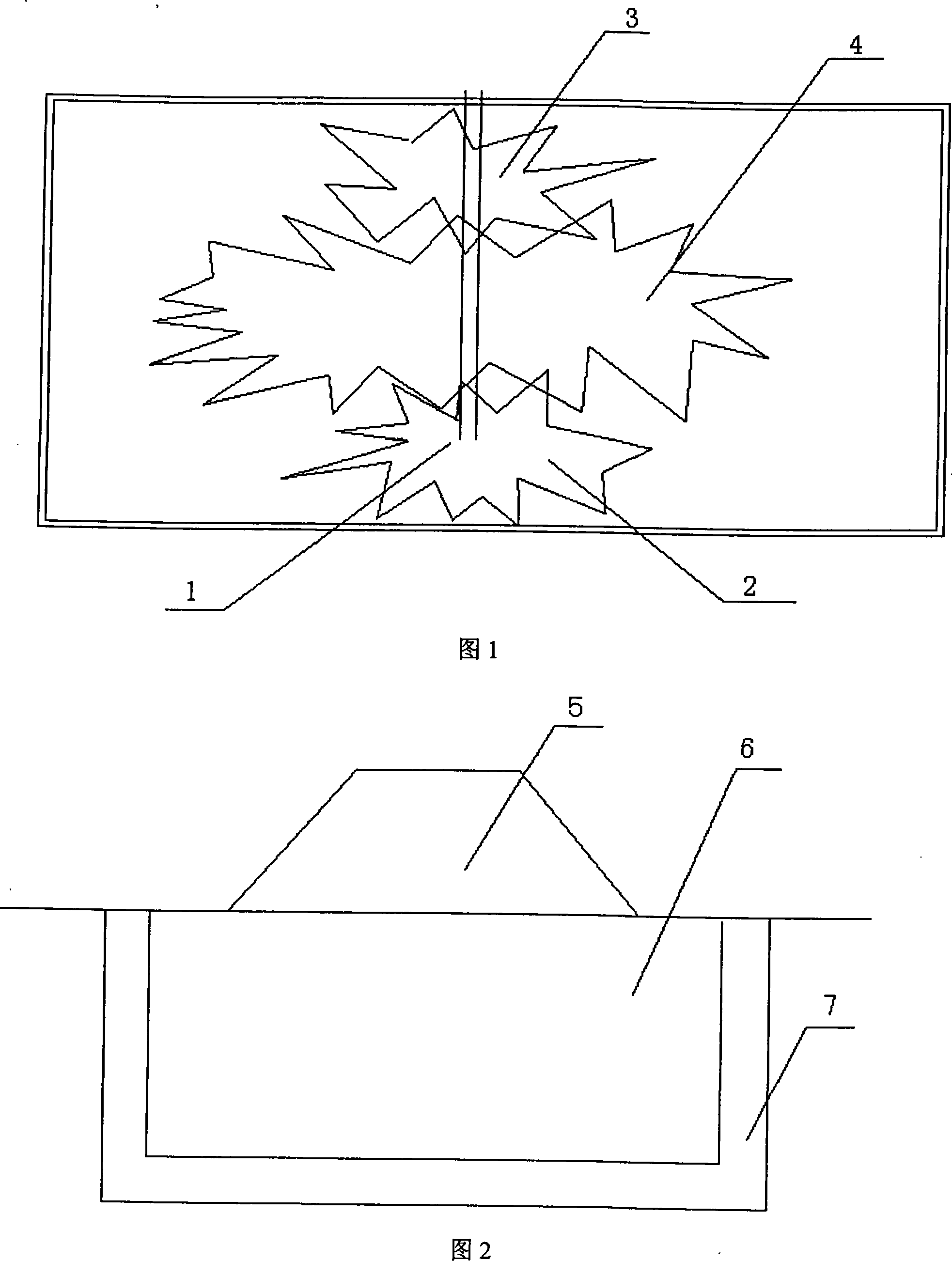

Image

  • Layered multitime pressure regulating pulp conditioning casting method
  • Layered multitime pressure regulating pulp conditioning casting method

Examples


Embodiment 1

[0027] Example 1: Take the reinforcement of the subgrade reinforced retaining wall of a national highway Jiehe overpass as an example. The overpass is constructed with reinforced earth retaining wall technology. The width of the approach bridge at the north and south ends is 14m, the length of the north end of the approach bridge is 156m, and the length of the south end of the approach bridge is 372m. The external bulging phenomenon of the wall gradually intensified, and longitudinal cracking occurred locally on the pavement.

[0028] In the retaining wall filled with loam containing a large number of pebbles, the "layered multiple pressure adjustment and grouting method" was carried out. As shown in FIG. 2 , the structure 5 , the reinforcement area 6 and the pulp stop belt 7 are determined.

[0029] (1) Stake out the reinforcement area 6, and determine the position and depth of the stop belt 7;

[0030] (2) In the axial direction of the grouting hole, the distribution of the...

Embodiment 2

[0040] The same as Example 1, the difference is that the retaining wall is reinforced with prestressed bolts. Since the anchoring section is located in a loam layer containing a lot of pebbles, it cannot provide sufficient pullout resistance for the prestressed bolts. Therefore, the "layered and multiple pressure regulation and grouting grouting method" is adopted for the prestressed bolt to improve its ultimate ultimate bearing capacity.

[0041] The length of the primary grouting pipe is roughly the same as that of the bolt, and no processing is required; the length of the secondary grouting pipe is the same as that of the bolt, and the inner port is sealed. , seal the hole with tape; three times of grouting pipe, the length is 4m, the inner port is sealed, and every 0.4m within the range of 2m at the inner end, the holes are drilled and sealed with tape; four times of grouting, the grouting pipe is larger than the anchor The length of the rod is 2m short, within the range f...


PUM


Abstract

The invention relates to a layered multiple pressure regulating grouting method which comprises the processing sequence: (1) a reinforced area is set up; the location and the depth of a grout stopping belt are determined; (2) the grouting soil distribution is determined according to different geological conditions, engineering features in the axial direction of a grouting hole; (3) a vary number of grouting pipes with different length are buried in the axial direction of a grouting hole according to different artesian conditions to cause grout to be spread in the designed different location; (4) a signal pole or soil sequencing holes of the reinforced area are repeatedly grouted. The invention has the characteristics of tangibility and strong pertinence, especially provides an efficient base process method for running grout, leaping grout caused by using a traditional grouting method in the geological conditions such as karst areas, large poriness when the fixing area is grouted and reinforced, and solves the deficiencies and shortcomings of the original construction technique through improving the techniques such as the grouting techniques, grouting materials, etc.

Description

technical field [0001] The invention relates to an engineering technology, in particular to a grouting method for multi-layered pressure regulation and grouting. Background technique [0002] At present, for common reinforcement projects such as karst areas, dams, roadbeds, retaining walls, and foundation pit support, it is often only necessary to deal with certain areas. Due to the poor geological conditions in the area, the traditional grouting technology cannot control the diffusion and loss of the slurry to the surrounding area, and it is easy to occur such phenomena as slurry running, slurry leakage, pollution and even endangering the safety of structures, resulting in a substantial increase in the project cost. However, the single-parameter and multi-layered multi-grouting construction technologies at home and abroad cannot grouting and reinforce the soil in a certain area, that is, the grouting construction scope cannot be accurately controlled, resulting in the dispe...

Claims


Application Information

Patent Timeline
Patent Type & Authority Applications(China)
IPC IPC(8): E02D3/12
Inventor 王松根宋修广李英勇张思峰张宏博管延华
Owner 山东省交通厅公路局
Why Eureka
Try Eureka