Large temperature-difference central heating system

A technology of central heating and large temperature difference, applied in steam central heating system, heating system, hot water central heating system, etc., can solve the problem of low energy utilization efficiency, achieve large heating temperature difference, reduce investment, supply The effect of low temperature of hot return water

Active Publication Date: 2008-07-30
TSINGHUA UNIV +1
View PDF2 Cites 127 Cited by
  • Summary
  • Abstract
  • Description
  • Claims
  • Application Information

AI Technical Summary

Problems solved by technology

However, in this process, since the heat network recovery does not directly recover the waste heat of the steam turbine condenser, only a part of the waste heat of the condenser can be

Method used


Image

  • Large temperature-difference central heating system

Examples


Embodiment 1

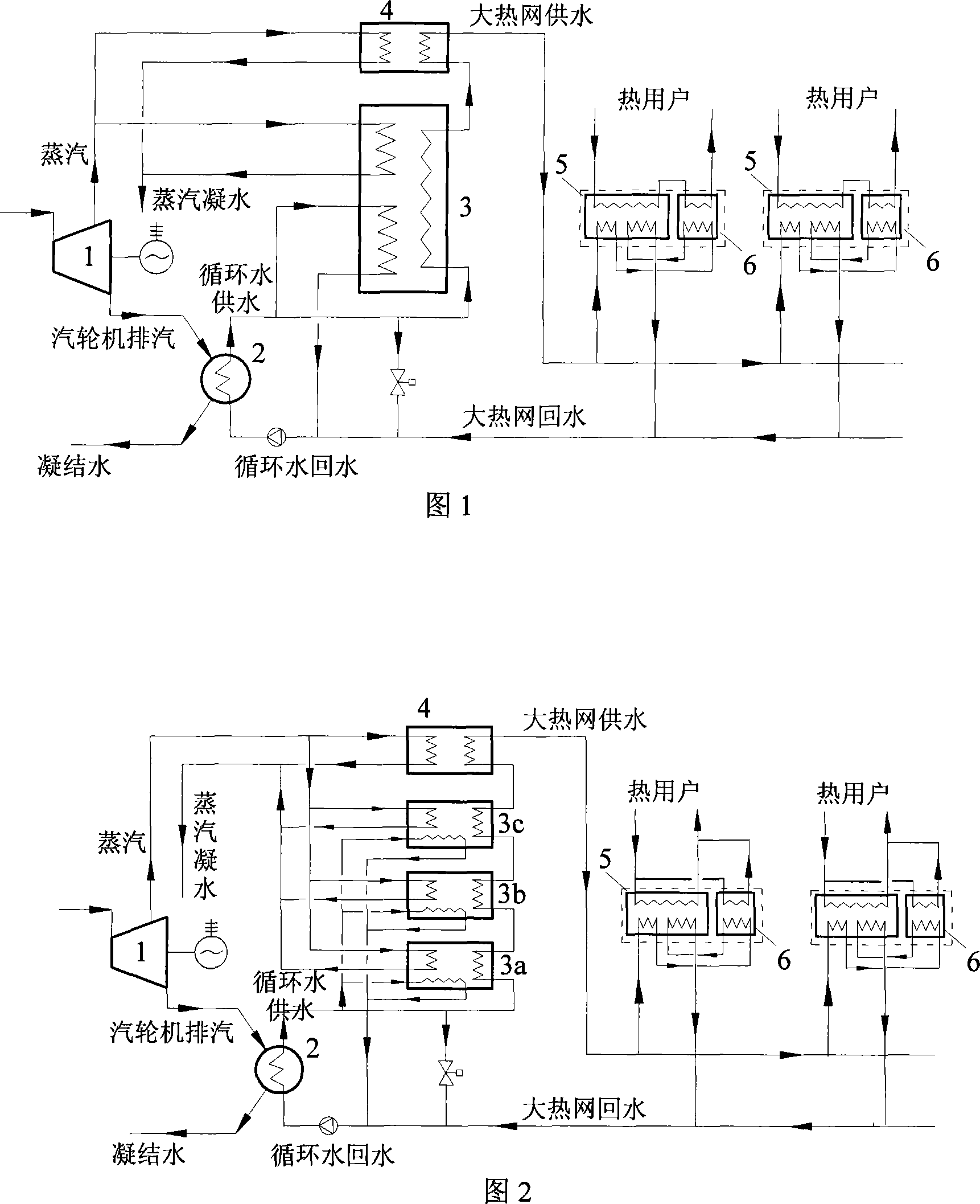
[0014] Example 1: Basic heating method. As shown in Figure 1, the system consists of a steam turbine 1, a condenser 2, a steam absorption heat pump 3, a steam-water heat exchanger 4, a hot water absorption heat pump 5, a water-water heat exchanger 6, and connecting pipes and accessories composition. The exhaust steam from the final stage of the steam turbine 1 enters the condenser 2 to heat the circulating water, and then returns to the boiler for heating after being cooled and condensed; the steam extracted from the steam turbine 1 is divided into two paths, and one path enters the steam absorption heat pump 3 as a driving heat source to recover the waste heat of the circulating water , and heat the large heating network, the other way enters the steam-water heat exchanger 5, directly heats the large heating network, and the steam condenses and returns to the boiler for heating; the circulating cooling water enters the condenser 1, is sent out after being heated by the exhaus...

Embodiment 2

[0016] Example 2: Three-stage steam absorption heat pumps are used for heating in series. As shown in Figure 2, the system consists of steam turbine 1, condenser 2, primary steam absorption heat pump 3a, secondary steam absorption heat pump 3b, tertiary steam absorption heat pump 3c, steam-water heat exchanger 4, hot water It consists of an absorption heat pump 5, a water-water heat exchanger 6, connecting pipelines and accessories. The exhaust steam from the final stage of steam turbine 1 enters the condenser 2 to heat the circulating water, and after being cooled and condensed, it returns to the boiler for heating; the steam extracted from steam turbine 1 is divided into two paths, and one path is used as a driving heat source to enter the first-stage steam absorption heat pump 3a and the second stage respectively. The first-stage steam absorption heat pump 3b and the third-stage steam absorption heat pump 3c recover the waste heat of the circulating water and heat the large...


PUM


Abstract

The invention relates to a central heating system with large temperature difference, which belongs to the energy field. The system comprises a steam turbine, a condenser, a steam absorption heat pump, a steam-water heat exchanger, a hot water absorption heat pump, a water-water heat exchanger as well as a connecting pipe and accessories. The invention is characterized in that the temperature difference of the heat net supply is large, and is about one time higher than the conventional heat net operation, thus the transmission capacity of the heat net is greatly increased, and at the same time, no heat preservation and thermal stress compensation problems exist as the backwater temperature of the heating is low, thereby reducing the investment of the backwater pipeline network and the whole pipeline network; the steam turbine is utilized to discharge steam and preheat the backwater of the large heat net, and circulating cooling water is utilized to be taken as the low level heat energy of the absorption heat pumps. The invention has the advantages that the residual heat produced in the electricity generating process of a power plant is recycled to the greatest extent as much as possible, the combination mode of the hot water absorption heat pump and the water-water heat exchanger is adopted at the end to heat the hot water of the secondary heat net supply, and the temperature difference of the supply-water and the backwater of the large heat net are increased, at the same time, the heat net does not need external energy to be the driving force.

Description

technical field [0001] The invention belongs to a central heating system with a large temperature difference. Compared with the conventional central heating system, this system can not only greatly increase the temperature difference between the supply and return water of high-temperature hot water, increase the transmission capacity of the heat network, but also effectively recover the steam turbine of the power plant. Exhaust heat. Background technique [0002] With the continuous development of the city scale, the urban central heating area continues to increase, and the heat source of central heating is developing to large-scale thermal power plants. These thermal power plants have two problems in heat supply. It is relatively small, and a large amount of waste heat is discharged from the cooling tower through the exhaust steam at the end of the steam turbine; secondly, because such a large-scale thermal power plant is far away from the heating load center, and the heati...

Claims


Application Information

Patent Timeline
IPC IPC(8): F24D9/00F24D1/02F24D1/08F24D3/18
CPCF01K7/38Y02B30/52Y02E20/14
Inventor 付林江亿张世钢肖常磊李永红胡鹏狄洪发陈闯
Owner TSINGHUA UNIV
Why Eureka
Try Eureka