
Device and method for real time on-line detecting flue gas pollutant

A technology for detecting devices and pollutants, applied in measuring devices, analysis of suspensions and porous materials, particle suspension analysis, etc., can solve the problems of inappropriateness, high manpower consumption, material resources, long test cycle, etc., to achieve easy detection, The effect of convenient operation and simple structure

Inactive Publication Date: 2008-07-30
SOUTH CENTRAL UNIVERSITY FOR NATIONALITIES
View PDF2 Cites 21 Cited by
  • Summary
  • Abstract
  • Description
  • Claims
  • Application Information

AI Technical Summary

Problems solved by technology

These two methods have greatly improved the detection accuracy of pollutants, but both must be completed in the laboratory, and the samples need to be pre-treated before the detection, so the requirements for the detection environment are strict, the test cycle is long, and it takes a lot human and material resources, so it is impossible to carry out real-time and effective control during the combustion process
At present, the devices for online detection of pollutant components only include single element analysis and vehicle exhaust detection, etc.
For example: an online atmospheric mercury analyzer (application number: 200510123603.1) can only analyze single element mercury
Another example: the infrared laser detection system and method (application number: 01141682.3) for real-time detection of automobile exhaust can monitor whether the automobile exhaust exceeds the standard in real time, but cannot determine the composition of its pollutants
These devices are not suitable for real-time online monitoring of various pollutants in flue gas during coal combustion
[0004] In view of the above reality, considering the complexity of flue gas components, and its online monitoring is in a high-temperature environment, at present, there is no device that can perform on-site, real-time, continuous detection of various pollutants in flue gas

Method used


Image

  • Device and method for real time on-line detecting flue gas pollutant

Examples


Embodiment Construction

[0019] Below in conjunction with accompanying drawing, the present invention will be further described.

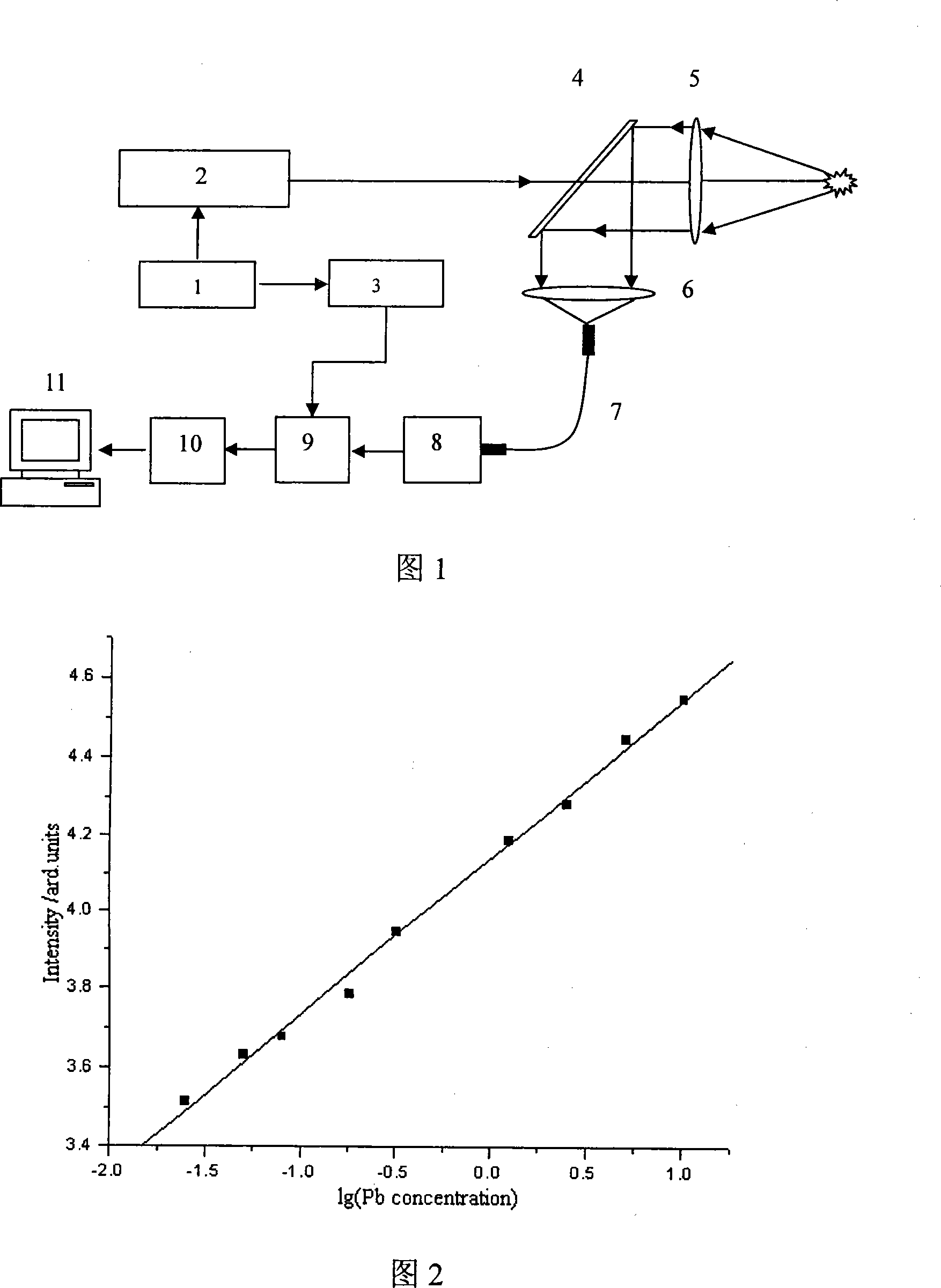
[0020] As shown in Figure 1, the real-time online detection device for smoke pollutants consists of a pulse generator 1, a pulse laser 2, a time delay device 3, a mirror 4, a long focal length focusing lens 5, a light receiver 6, an optical fiber 7, A spectrometer 8, a photodetector 9, an A / D converter 10 and a computer 11 are composed. The pulse generator 1 is respectively connected to the external trigger end of the pulse laser 2 and the input end of the time delay device 3; in the laser emission direction of the pulse laser 2, the mirror 4 and the long-focus lens 5 are arranged coaxially in sequence, and the optical receiver 6 The receiving end is arranged on the coaxial position of the reflection direction of the mirror 4, the output end of the optical receiver 6 is connected to the input end of the spectrometer 8 through the optical fiber 7, and the output end of the ...


PUM


Abstract

The invention discloses a real-time on-line detecting apparatus of smoke pollutant and the test method thereof, and relates to the atmospheric environmental monitoring. The apparatus comprises a pulse generator (1), a pulse laser (2), a time delayer (3), a reflector (4), a long-focus focusing lens (5), a light receiving device (6), optical fibre (7), a spectrometer (8), an A / D converter (10), and a computer (11). The invention utilizes a focused high energy laser beam to motivate the substance in the smoke gas to be the high energy state, various substances radiate respective characteristic spectrums during the process of the high energy state returning the base state, the composition of the pollutant such as magnesium, iron, copper, aluminum, lead, chrome, hydrargyrum, arsenic, etc. in the tested smoke gas and the concentration thereof can be obtained by analyzing the characteristic spectrums. The invention has the advantages of simple structure, reliable method and convenient operation, and is suitable for performing the real-time and on-line continuous detection of the pipeline smoke gas during the combustion process of coal.

Description

technical field [0001] The invention relates to atmospheric environment monitoring, and is mainly used for real-time on-line detection of various pollutants in pipeline flue gas during coal combustion. Background technique [0002] With the need for sustainable development and the improvement of environmental protection awareness, human beings have begun to pay attention to the hazards of air pollution. The latest scientific research shows that the flue gas produced by coal combustion is the main source of air pollution and has become the main target of environmental governance. How to effectively control the combustion process and the emission of combustion pollutants has gradually become a focus of increasing attention from government departments and scientific research institutions. The premise of controlling the emission of pollutants in the flue gas is to know the composition and content of the pollutants, and the real-time online measurement, the detection results can...

Claims


Application Information

Patent Timeline
IPC IPC(8): G01N21/63G01N15/06
Inventor 林兆祥张文艳孙奉娄宋述燕
Owner SOUTH CENTRAL UNIVERSITY FOR NATIONALITIES
Learn More